
- Difficulty
- Advanced
- Build time
- 120-180 min
- Estimated cost
- $0-$25
- Age range
- 13-18
- Workspace
- A clear table about 90 cm wide
The finish line
What you will build
The foot point traces a repeatable loop whose working section deviates by less than about 8 mm from a straight reference over 8 cm of travel.
Learning goals
- Identify how rotation of a short crank produces foot point with near-straight stance motion.
- Construct and explain a rotary-to-planar walking path system.
- Measure how the foot-point location on the coupler changes performance.
- Diagnose losses caused by pivot clearance and link flex.
Before you build
Materials, tools, and safety
Reuse-material cost: Usually under $5 with an existing kit. Supervision: Adult help recommended for sharp or heated tools.
Tools
- Ruler
- Removable tape for motion marks
Low-cost swaps
- Use equivalent brick-compatible parts from any kit.
- Use cardboard beams and straw bearings for a larger demonstration model.
- Cut links from laminated cardstock and use brass paper fasteners for a large tracing model.
Project-specific safety
- Keep fingers, hair, and loose sleeves clear of moving parts.
- Turn the mechanism by hand; do not attach a high-speed motor.
- Use as an unloaded kinematic model and keep hands clear of crossing links.
Orient the build
Place the build so rotation of a short crank is on your left and foot point with near-straight stance motion is on your right. Call the side facing you the front, the far side the back, the tabletop the bottom, and the opposite face the top.
Build it
Step-by-step instructions
Step 1
Prepare the proportion set
Measure every center-to-center length from one scale and label each link.
Do not round different links independently.
Step 2
Build the ground base
Place two reinforced pivots at the specified spacing on parallel walls.
Check the base against a ruler line.
Step 3
Attach the input crank
Mount the shortest link at the first ground pivot with a slow handle.
Mark its starting angle.
Builder checkpoint: After attach the input crank, the first subassembly should stay aligned when handled gently.
Step 4
Attach the rocker
Mount the output link at the second ground pivot in the chosen branch.
Keep both moving links in separate planes.
Watch for: If this stage binds or drifts, inspect foot drag before adding more parts.
Step 5
Join with the coupler
Connect crank and rocker free ends with the measured coupler.
Verify all pivots remain free.
Step 6
Add the foot point
Extend or mark the specified coupler location with a blunt tracer.
Keep the marker perpendicular to paper.
Builder checkpoint: After add the foot point, operate the build slowly and confirm that foot point with near-straight stance motion begins without binding.
Step 7
Check full rotation
Turn through 360 degrees in 30-degree steps and inspect locks or collisions.
Correct geometry before tracing.
Step 8
Trace the path
Hold the base fixed and draw one closed cycle.
Use a ruler to measure straight-section deviation.
Builder checkpoint: At the final checkpoint, The foot point traces a repeatable loop whose working section deviates by less than about 8 mm from a straight reference over 8 cm of travel.
See the engineering
Why it works
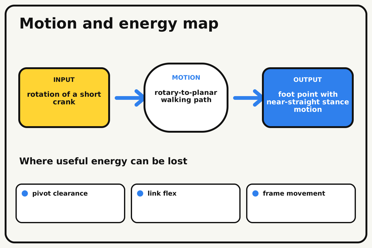
- Input
- rotation of a short crank
- Output
- foot point with near-straight stance motion
- Motion
- rotary-to-planar walking path
- Energy losses
- pivot clearance, link flex, frame movement, foot drag
Why this works
Approximate straight-line linkage
A chosen four-bar proportion shapes the coupler point path so one section approximates a line. The rest of the cycle returns the point in a curved loop.
Look for: Trace the endpoint and compare the stance section with a ruler line rather than judging by eye.
Where the energy goes
Efficiency and losses
The ideal model leaves out pivot clearance, link flex, frame movement, foot drag. These effects turn some input energy into heat, sound, vibration, or unwanted motion, so measured performance will be lower than an ideal calculation.
Look for: Run the build slowly and locate the first place where pivot clearance becomes visible or audible.
Math bite
Measure straightness error
Formula: maximum deviation = largest |measured height - reference height|
- Reference line height = 40 mm
- Largest measured height = 47 mm
Substitute: deviation = |47 - 40| = 7 mm
Result: The working path departs from straight by at most 7 mm.
Smaller error is useful, but foot travel and clearance also matter.
Marker thickness and pivot play add measurement error.
Make it behave
Test, troubleshoot, and tune
Controlled test
Start here: Trace one unloaded foot cycle at slow hand speed.
Success looks like: The path closes and its selected stance section stays within 8 mm of a ruler line.
Measure: Straight-section length and maximum vertical deviation.
Change: the foot-point location on the coupler
Keep constant: link lengths, ground spacing, frame, crank start, and marker
- inner point
- reference point
- outer point
| Symptom | Likely cause | Confirm it | Fix |
|---|---|---|---|
| The crank locks | Lengths or assembly branch are incorrect | Move to the lock without force and compare geometry | Return to verified proportions and uncross links |
| The trace does not close | A pivot or base shifts | Mark every ground point before a second cycle | Brace and retain all pivots |
| The line section is strongly curved | Foot point or link scale is wrong | Measure point position from pivot centers | Correct the coupler point and lengths |
| Links scrape | They occupy the same depth layer | Watch overlaps through the cycle | Add spacers and separate planes |
Choose your tradeoff
Judge path quality from measurements, not appearance. Change only the foot-point location first; altering core link proportions can remove full crank rotation.
Keep experimenting
Try another version
Pinned paper model
Explore the path on a flat sheet with no rigid frame.
Foot-point sweep
Trace three points on the same coupler.
Compare walkers
Overlay this path with a Jansen leg trace at the same scale.
Build together
Classroom and access options
Classroom version
Teams can compare the foot-point location on the coupler while keeping link lengths, ground spacing, frame, crank start, and marker. Assign builder, tester, recorder, and explainer roles; have each team predict the result before collecting three trials.
Access adaptations
- Use high-contrast tape to distinguish input and output parts.
- Replace a small crank with a wider handle for an easier grip.
- Use three high-contrast link colors and raised ground-pivot labels.
Reflect on the design
- How did the foot-point location on the coupler change the measured result?
- Where did pivot clearance affect the build most strongly?
- What evidence shows that approximate straight-line linkage explains the motion?
- Which change would improve foot point with near-straight stance motion without creating a new problem?
Glossary
- Approximate straight-line linkage
- A chosen four-bar proportion shapes the coupler point path so one section approximates a line.
- Input
- The action or energy supplied to a system; here it is rotation of a short crank.
- Output
- The useful response produced by a system; here it is foot point with near-straight stance motion.
- Efficiency
- The fraction of input energy that becomes useful output instead of friction, sound, heat, or unwanted motion.
Build your dreams
One build can start the next.
Share what you learned, change one variable, and help another builder understand what worked.
Explore more guidesSources and build notes
An original BrickLabClips interpretation of a standard mechanical mechanism.
- Mechanism verification: Standard kinematics were checked for motion direction, constraint, clearance, and likely friction points.
Written and edited by BrickLabClips. Published 2026-07-22; updated 2026-07-22.