
- Difficulty
- Advanced
- Build time
- 90-140 min
- Estimated cost
- $0-$20
- Age range
- 13-18
- Workspace
- A clear table about 90 cm wide
The finish line
What you will build
The output flag remains reliably in state 0 or state 1 after release and changes state only when the matching set or reset input is pressed.
Learning goals
- Identify how separate set and reset lever pushes produces one stored two-position flag.
- Construct and explain a reciprocating inputs-to-bistable angular output system.
- Measure how the elastic preload changes performance.
- Diagnose losses caused by pivot friction and spring hysteresis.
Before you build
Materials, tools, and safety
Reuse-material cost: Usually under $5 with an existing kit. Supervision: Adult help recommended for sharp or heated tools.
Tools
- Ruler
- Removable tape for motion marks
Low-cost swaps
- Use equivalent brick-compatible parts from any kit.
- Use cardboard beams and straw bearings for a larger demonstration model.
- Use a craft-stick rocker and a lightly stretched rubber band between two cardboard anchor points.
Project-specific safety
- Keep fingers, hair, and loose sleeves clear of moving parts.
- Turn the mechanism by hand; do not attach a high-speed motor.
- Use a weak elastic element and shield its anchors; stop if any band shows damage.
Orient the build
Place the build so separate set and reset lever pushes is on your left and one stored two-position flag is on your right. Call the side facing you the front, the far side the back, the tabletop the bottom, and the opposite face the top.
Build it
Step-by-step instructions
Step 1
Build the rocker frame
Mount one output lever on a reinforced center pivot with room to swing both ways.
Add equal left and right travel stops.
Step 2
Create over-center bias
Connect a light elastic element so its force line crosses the rocker pivot near center.
Begin with low tension.
Step 3
Mark stable states
Move gently to both stops and confirm the spring holds each position.
Label them 0 and 1.
Builder checkpoint: After mark stable states, the first subassembly should stay aligned when handled gently.
Step 4
Add the set lever
Place a returning push lever that moves the rocker from 0 past center toward 1.
Add a stop before collision.
Watch for: If this stage binds or drifts, inspect link backlash before adding more parts.
Step 5
Add the reset lever
Mirror a second returning lever for movement from 1 toward 0.
Keep input links in separate planes.
Step 6
Tune threshold travel
Press each input slowly and mark when the rocker crosses center.
Ensure partial presses do not change state.
Builder checkpoint: After tune threshold travel, operate the build slowly and confirm that one stored two-position flag begins without binding.
Step 7
Test memory
Set state 1, release every input, wait five seconds, then reset to 0.
Tap the frame lightly between tests.
Step 8
Run a state sequence
Perform 0-set-1-reset-0-set-1 ten times.
Record missed switches and unintended changes.
Builder checkpoint: At the final checkpoint, The output flag remains reliably in state 0 or state 1 after release and changes state only when the matching set or reset input is pressed.
See the engineering
Why it works
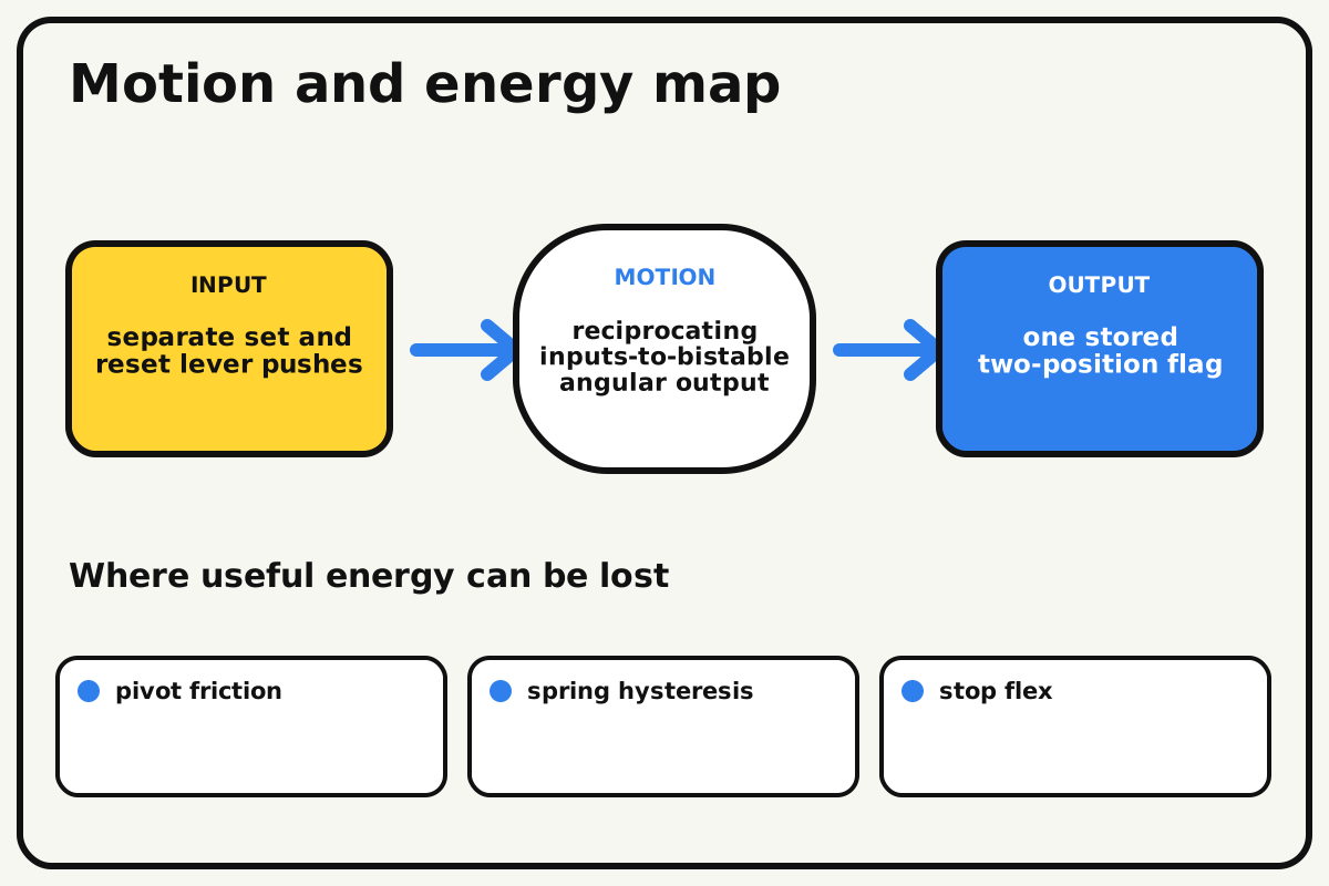
- Input
- separate set and reset lever pushes
- Output
- one stored two-position flag
- Motion
- reciprocating inputs-to-bistable angular output
- Energy losses
- pivot friction, spring hysteresis, stop flex, link backlash
Why this works
Bistable energy landscape
An over-center spring or toggle has two low-energy positions separated by an unstable center. A sufficient input crosses the center barrier, after which stored elastic energy completes and holds the new state.
Look for: Move the output slowly toward center and feel the direction of spring force reverse after the toggle point.
Where the energy goes
Efficiency and losses
The ideal model leaves out pivot friction, spring hysteresis, stop flex, link backlash. These effects turn some input energy into heat, sound, vibration, or unwanted motion, so measured performance will be lower than an ideal calculation.
Look for: Run the build slowly and locate the first place where pivot friction becomes visible or audible.
Math bite
Compare spring moments
Formula: moment = spring force × perpendicular offset
- Spring force = 2 N
- Offset from pivot = 0.015 m
Substitute: moment = 2 × 0.015 = 0.03 N·m
Result: The spring creates 0.03 newton-metres toward a stable stop.
At center, the offset changes sign and the preferred state switches.
Elastic force varies with stretch and geometry.
Make it behave
Test, troubleshoot, and tune
Controlled test
Start here: Place the output in state 0 and release all inputs for five seconds.
Success looks like: Each state holds after release and only the correct input causes a transition.
Measure: Successful state changes and false changes in ten commands.
Change: the elastic preload
Keep constant: rocker, stops, input travel, frame taps, sequence, and wait time
- low preload
- moderate preload
- higher safe preload
| Symptom | Likely cause | Confirm it | Fix |
|---|---|---|---|
| The output rests at center | Over-center geometry or spring force is insufficient | Move slightly left and right and release | Shift spring anchor past the pivot line |
| It changes state from vibration | Barrier is too small or stops flex | Tap the base gently in each state | Increase safe preload or over-center distance |
| A button cannot switch state | Input travel ends before center crossing | Watch rocker during full press | Move the input link or increase travel stop |
| Set also triggers reset | Input linkages collide | Press each button while observing the other | Separate linkage planes and add return stops |
Choose your tradeoff
Increase the state barrier only enough to survive normal handling. Too much preload makes inputs difficult and stresses parts; firm stops and clear center crossing improve reliability.
Keep experimenting
Try another version
Hand-flipped rocker
Build the two stable states without set/reset levers.
Memory indicator
Use the state to reveal one of two messages.
Two-bit register
Connect two modules and record four possible states.
Build together
Classroom and access options
Classroom version
Teams can compare the elastic preload while keeping rocker, stops, input travel, frame taps, sequence, and wait time. Assign builder, tester, recorder, and explainer roles; have each team predict the result before collecting three trials.
Access adaptations
- Use high-contrast tape to distinguish input and output parts.
- Replace a small crank with a wider handle for an easier grip.
- Shape the set and reset buttons differently and add a clicker at each state stop.
Reflect on the design
- How did the elastic preload change the measured result?
- Where did pivot friction affect the build most strongly?
- What evidence shows that bistable energy landscape explains the motion?
- Which change would improve one stored two-position flag without creating a new problem?
Glossary
- Bistable energy landscape
- An over-center spring or toggle has two low-energy positions separated by an unstable center.
- Input
- The action or energy supplied to a system; here it is separate set and reset lever pushes.
- Output
- The useful response produced by a system; here it is one stored two-position flag.
- Efficiency
- The fraction of input energy that becomes useful output instead of friction, sound, heat, or unwanted motion.
Build your dreams
One build can start the next.
Share what you learned, change one variable, and help another builder understand what worked.
Explore more guidesSources and build notes
An original BrickLabClips interpretation of a standard mechanical mechanism.
- Mechanism verification: Standard kinematics were checked for motion direction, constraint, clearance, and likely friction points.
Written and edited by BrickLabClips. Published 2026-07-22; updated 2026-07-22.