
- Difficulty
- Advanced
- Build time
- 90-140 min
- Estimated cost
- $0-$20
- Age range
- 13-18
- Workspace
- A clear table about 90 cm wide
The finish line
What you will build
The output flag activates only for input state 1,1 and remains inactive for 0,0, 1,0, and 0,1 across three repeated truth-table trials.
Learning goals
- Identify how two independent binary lever positions produces one permitted slider position.
- Construct and explain a two angular inputs-to-binary linear output system.
- Measure how the input combination changes performance.
- Diagnose losses caused by slider friction and lever backlash.
Before you build
Materials, tools, and safety
Reuse-material cost: Usually under $5 with an existing kit. Supervision: Adult help recommended for sharp or heated tools.
Tools
- Ruler
- Removable tape for motion marks
Low-cost swaps
- Use equivalent brick-compatible parts from any kit.
- Use cardboard beams and straw bearings for a larger demonstration model.
- Use cardboard levers, clothespin returns, and a paper output slider for a large classroom logic model.
Project-specific safety
- Keep fingers, hair, and loose sleeves clear of moving parts.
- Turn the mechanism by hand; do not attach a high-speed motor.
- Use light return forces and rounded lever ends so no blocker snaps into fingers.
Orient the build
Place the build so two independent binary lever positions is on your left and one permitted slider position is on your right. Call the side facing you the front, the far side the back, the tabletop the bottom, and the opposite face the top.
Build it
Step-by-step instructions
Step 1
Build the output guide
Create a low-friction slider path with inactive and active stops.
Add a visible output flag.
Step 2
Install blocker A
Place a tab that blocks output when input A is at zero.
Link it to a lever with two stable stops.
Step 3
Install blocker B
Add a second independent tab farther along the same output path.
Connect it to its own labeled lever.
Builder checkpoint: After install blocker b, the first subassembly should stay aligned when handled gently.
Step 4
Add gentle resets
Return each input to zero and the output to inactive after release.
Check that bands do not bend the frame.
Watch for: If this stage binds or drifts, inspect return-band drag before adding more parts.
Step 5
Verify zero-zero
Set both inputs to zero and push output gently.
Both blockers should remain in the path.
Step 6
Test single inputs
Set A only, then B only, resetting between tests.
The remaining blocker must stop output each time.
Builder checkpoint: After test single inputs, operate the build slowly and confirm that one permitted slider position begins without binding.
Step 7
Test both inputs
Set A and B to one and move output to active.
Confirm both tabs clear without rubbing.
Step 8
Run the truth table
Repeat all four states three times in shuffled order.
Record output as 0 or 1 for every trial.
Builder checkpoint: At the final checkpoint, The output flag activates only for input state 1,1 and remains inactive for 0,0, 1,0, and 0,1 across three repeated truth-table trials.
See the engineering
Why it works
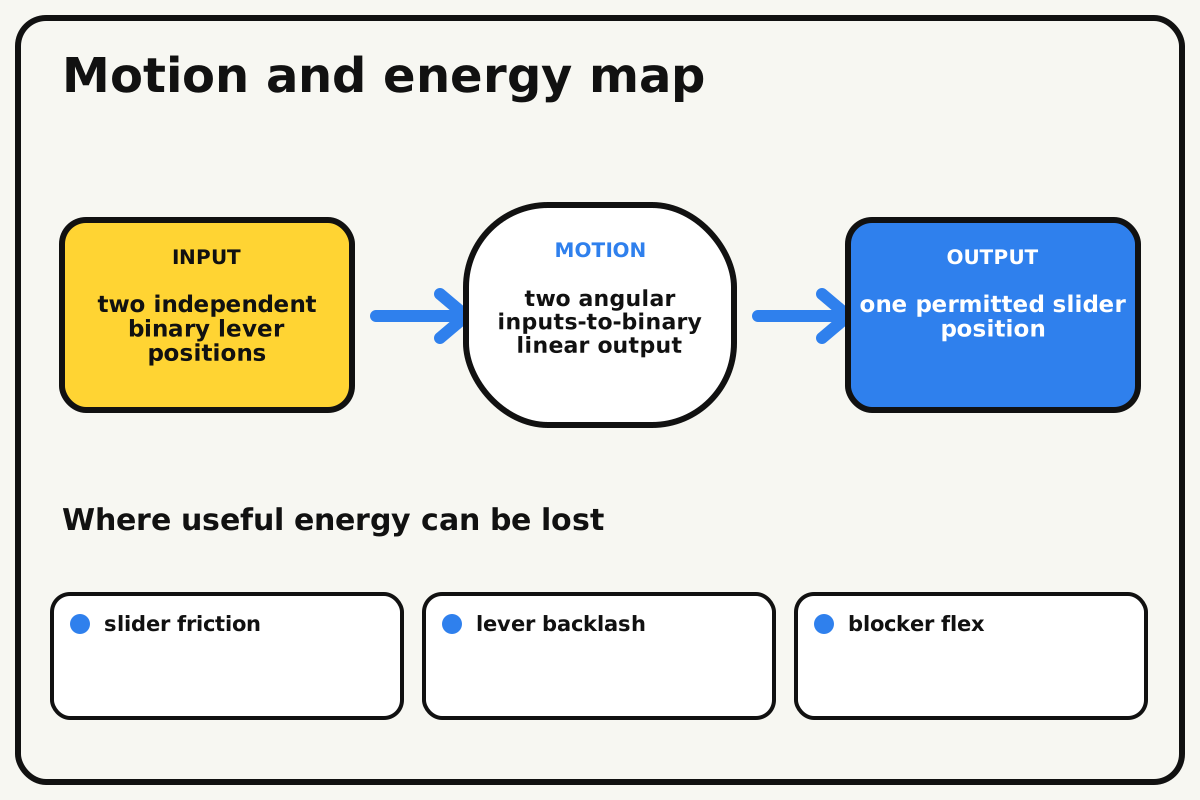
- Input
- two independent binary lever positions
- Output
- one permitted slider position
- Motion
- two angular inputs-to-binary linear output
- Energy losses
- slider friction, lever backlash, blocker flex, return-band drag
Why this works
AND truth condition
Two blockers independently prevent output travel. Input A removes one blocker and input B removes the other, so the output path opens only when both inputs are active.
Look for: Test all four input combinations in a fixed order and compare the output with an AND truth table.
Where the energy goes
Efficiency and losses
The ideal model leaves out slider friction, lever backlash, blocker flex, return-band drag. These effects turn some input energy into heat, sound, vibration, or unwanted motion, so measured performance will be lower than an ideal calculation.
Look for: Run the build slowly and locate the first place where slider friction becomes visible or audible.
Math bite
Evaluate the AND output
Formula: Y = A × B for binary inputs
- A = 1
- B = 0
Substitute: Y = 1 × 0 = 0
Result: One inactive input keeps the output inactive.
Only 1 × 1 produces output 1.
Mechanical clearance may create an ambiguous state if stops are poorly set.
Make it behave
Test, troubleshoot, and tune
Controlled test
Start here: Set both inputs to zero and confirm the output stop.
Success looks like: Only state 1,1 activates the output in every repeated trial.
Measure: Correct outputs out of twelve truth-table trials.
Change: the input combination
Keep constant: frame, blockers, output force, stop positions, and reset order
- 00 and 10
- 01 and 11
- all states in shuffled order
| Symptom | Likely cause | Confirm it | Fix |
|---|---|---|---|
| Output moves with one input | A blocker is too short or misses the slider | Test A-only and B-only separately | Lengthen and realign the failing blocker |
| Output stays blocked at 11 | One tab does not fully clear | Hold both levers at stops and inspect path | Increase lever travel or tab clearance |
| Inputs change each other | Lever links collide or share a flexible mount | Move one input while watching the other | Separate planes and brace pivots |
| The truth table varies | Stops or resets are not repeatable | Mark lever positions for each trial | Add firm detents and reduce backlash |
Choose your tradeoff
Clear binary stops are more important than tiny clearances. Design generous blocked and clear positions so normal joint play cannot change the logical result.
Keep experimenting
Try another version
One blocker demo
Show how one binary lever permits or blocks output.
Mechanical alarm
Let the output ring a paper bell only when both conditions are true.
NAND conversion
Invert the final output and verify the new truth table.
Build together
Classroom and access options
Classroom version
Teams can compare the input combination while keeping frame, blockers, output force, stop positions, and reset order. Assign builder, tester, recorder, and explainer roles; have each team predict the result before collecting three trials.
Access adaptations
- Use high-contrast tape to distinguish input and output parts.
- Replace a small crank with a wider handle for an easier grip.
- Use tactile 0 and 1 detents plus different shapes for A, B, and output.
Reflect on the design
- How did the input combination change the measured result?
- Where did slider friction affect the build most strongly?
- What evidence shows that and truth condition explains the motion?
- Which change would improve one permitted slider position without creating a new problem?
Glossary
- AND truth condition
- Two blockers independently prevent output travel.
- Input
- The action or energy supplied to a system; here it is two independent binary lever positions.
- Output
- The useful response produced by a system; here it is one permitted slider position.
- Efficiency
- The fraction of input energy that becomes useful output instead of friction, sound, heat, or unwanted motion.
Build your dreams
One build can start the next.
Share what you learned, change one variable, and help another builder understand what worked.
Explore more guidesSources and build notes
An original BrickLabClips interpretation of a standard mechanical mechanism.
- Mechanism verification: Standard kinematics were checked for motion direction, constraint, clearance, and likely friction points.
Written and edited by BrickLabClips. Published 2026-07-22; updated 2026-07-22.