
- Difficulty
- Advanced
- Build time
- 150-240 min
- Estimated cost
- $0-$12
- Age range
- 13-18
- Workspace
- A clear table about 90 cm wide
The finish line
What you will build
The creature completes five hand-cranked cycles, advances at least 20 cm on a test mat, and keeps all leg pivots attached.
Learning goals
- Identify how hand rotation of a phased crankshaft produces alternating leg motion and forward body travel.
- Construct and explain a rotary-to-cyclic walking translation system.
- Measure how the crank phase between leg pairs changes performance.
- Diagnose losses caused by foot slip and pivot friction.
Before you build
Materials, tools, and safety
Reuse-material cost: Usually under $5 with an existing kit. Supervision: Adult help recommended for sharp or heated tools.
Tools
- Ruler
- Pencil
- Scissors
- Low-temperature glue gun or tape
- Straight dowels
- Hole punch
- Adult-operated craft knife
Low-cost swaps
- Use clean shipping-box cardboard instead of buying sheets.
- Replace hot glue with strong tape and folded tabs.
- Build one leg module as a tracing model before constructing the full creature.
Project-specific safety
- An adult should handle craft knives and make difficult starter cuts.
- Let hot glue cool before pressing a joint or testing moving parts.
- Operate only as a lightweight tabletop or floor model; do not sit, stand, or ride on the build.
Orient the build
Place the build so hand rotation of a phased crankshaft is on your left and alternating leg motion and forward body travel is on your right. Call the side facing you the front, the far side the back, the tabletop the bottom, and the opposite face the top.
Build it
Step-by-step instructions
Step 1
Prototype one leg
Build one measured linkage and trace its foot path beside the body.
Correct locks before making copies.
Step 2
Duplicate mirrored legs
Overlay templates so all pivot-center distances match.
Label front-left, front-right, rear-left, and rear-right.
Step 3
Build the stiff body
Laminate the long beam and add bearing boxes around the crankshaft.
Brace against twisting.
Builder checkpoint: After build the stiff body, the first subassembly should stay aligned when handled gently.
Step 4
Make the phased crankshaft
Set opposing crank pins 180 degrees apart and secure them against rotation.
Mark phase positions visibly.
Watch for: If this stage binds or drifts, inspect leg collisions before adding more parts.
Step 5
Attach leg pivots
Mount mirrored legs on separate depth planes with equal body spacing.
Check free motion while the body is lifted.
Step 6
Add foot pads
Place flexible high-friction pads below every foot point.
Keep return feet from catching edges.
Builder checkpoint: After add foot pads, operate the build slowly and confirm that alternating leg motion and forward body travel begins without binding.
Step 7
Run suspended cycles
Turn five slow cycles with the body supported above the mat.
Resolve every link collision and tight angle.
Step 8
Run floor trials
Place on the marked mat and turn at one cycle every three seconds.
Measure distance, drift, slips, and falls over five cycles.
Builder checkpoint: At the final checkpoint, The creature completes five hand-cranked cycles, advances at least 20 cm on a test mat, and keeps all leg pivots attached.
See the engineering
Why it works
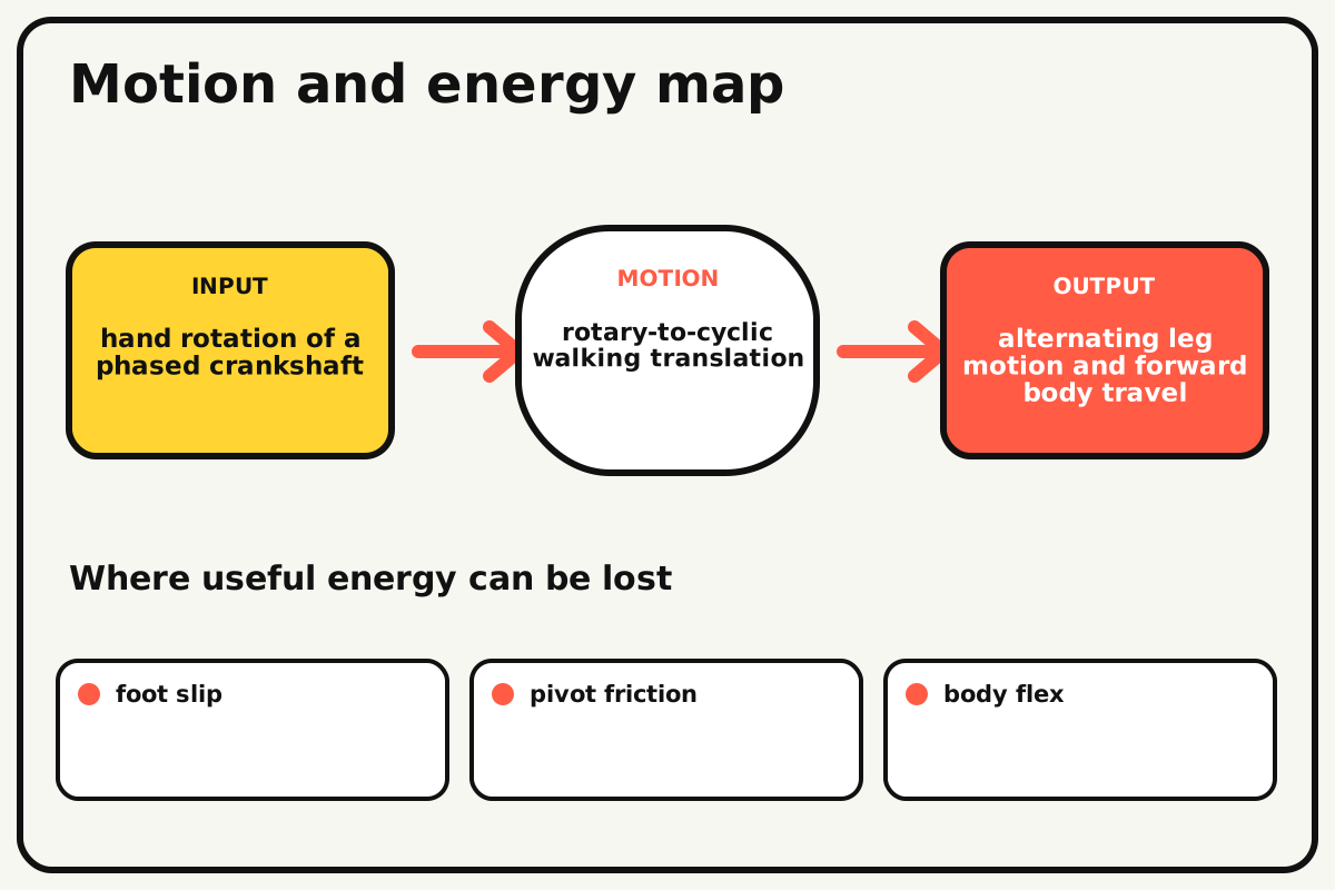
- Input
- hand rotation of a phased crankshaft
- Output
- alternating leg motion and forward body travel
- Motion
- rotary-to-cyclic walking translation
- Energy losses
- foot slip, pivot friction, body flex, leg collisions
Why this works
Alternating support gait
Leg pairs offset in phase move one set through stance while another returns. Forward travel occurs when stance feet grip the ground more strongly than returning feet drag.
Look for: Mark each foot's stance and return phases during one suspended crank cycle before floor testing.
Where the energy goes
Efficiency and losses
The ideal model leaves out foot slip, pivot friction, body flex, leg collisions. These effects turn some input energy into heat, sound, vibration, or unwanted motion, so measured performance will be lower than an ideal calculation.
Look for: Run the build slowly and locate the first place where foot slip becomes visible or audible.
Math bite
Measure stride efficiency
Formula: advance per cycle = total distance / cycles
- Distance = 0.20 m
- Cycles = 5
Substitute: advance = 0.20/5 = 0.04 m
Result: The creature advances 4 cm per crank cycle.
Foot-path length may be larger because some motion slips.
Surface friction and body sway change results.
Make it behave
Test, troubleshoot, and tune
Controlled test
Start here: Run five suspended crank cycles before contacting the floor.
Success looks like: The creature completes five floor cycles and advances at least 20 cm without a pivot failure.
Measure: Distance per cycle, sideways drift, foot slips, and falls.
Change: the crank phase between leg pairs
Keep constant: body, legs, feet, surface, crank rate, and five-cycle duration
- 180-degree phase
- slightly earlier rear phase
- slightly later rear phase
| Symptom | Likely cause | Confirm it | Fix |
|---|---|---|---|
| The creature moves backward | Foot path or crank direction reverses stance | Trace one foot while suspended | Reverse crank direction or leg orientation |
| It falls sideways | Support polygon is narrow or phases align poorly | Pause at several crank angles | Widen feet and adjust side phase |
| Feet slide without travel | Pad friction is low or return feet drag | Watch each contact phase | Improve pads and raise return path |
| Legs collide | Mirrored links share depth planes | Turn suspended to the contact point | Add spacers and separate layers |
Choose your tradeoff
Stability and foot clearance come before stride length. Stiffer bodies preserve phase; grippier feet help stance but can increase return drag if the foot path is too low.
Keep experimenting
Try another version
One-sided walker
Build and trace one leg pair without body travel.
Foot-pad study
Compare paper, foam, and rubberized surfaces.
Four-phase gait
Offset each leg by 90 degrees and map stability.
Build together
Classroom and access options
Classroom version
Teams can compare the crank phase between leg pairs while keeping body, legs, feet, surface, crank rate, and five-cycle duration. Assign builder, tester, recorder, and explainer roles; have each team predict the result before collecting three trials.
Access adaptations
- Pre-cut repeated pieces and mark fold lines with high-contrast ink.
- Use large tabs, binder clips, and tape for easier one-handed assembly.
- Color-code mirrored leg pairs and provide a large side crank with a comfortable grip.
Reflect on the design
- How did the crank phase between leg pairs change the measured result?
- Where did foot slip affect the build most strongly?
- What evidence shows that alternating support gait explains the motion?
- Which change would improve alternating leg motion and forward body travel without creating a new problem?
Glossary
- Alternating support gait
- Leg pairs offset in phase move one set through stance while another returns.
- Input
- The action or energy supplied to a system; here it is hand rotation of a phased crankshaft.
- Output
- The useful response produced by a system; here it is alternating leg motion and forward body travel.
- Efficiency
- The fraction of input energy that becomes useful output instead of friction, sound, heat, or unwanted motion.
Build your dreams
One build can start the next.
Share what you learned, change one variable, and help another builder understand what worked.
Explore more guidesSources and build notes
An original BrickLabClips cardboard machine with dimensionally specified construction.
- Cardboard design verification: Dimensions, fold allowances, repeated-motion joints, and likely load paths received an editorial geometry review.
Written and edited by BrickLabClips. Published 2026-07-22; updated 2026-07-22.