
- Difficulty
- Intermediate
- Build time
- 90-140 min
- Estimated cost
- $0-$8
- Age range
- 11-17
- Workspace
- A clear table about 90 cm wide
The finish line
What you will build
The character repeats one complete motion per crank turn for ten cycles, reaches the same high and low positions, and does not catch on the scenery.
Learning goals
- Identify how hand-crank rotation produces timed character lift or swing.
- Construct and explain a rotary-to-reciprocating scenic motion system.
- Measure how the cam high-dwell angle changes performance.
- Diagnose losses caused by follower rubbing and cam wobble.
Before you build
Materials, tools, and safety
Reuse-material cost: $0-$3 with reused materials. Supervision: Adult help recommended for sharp or heated tools.
Tools
- Ruler
- Pencil
- Scissors
- Low-temperature glue gun or tape
- Adult-operated craft knife
- Skewer or dowel
Low-cost swaps
- Use clean shipping-box cardboard instead of buying sheets.
- Replace hot glue with strong tape and folded tabs.
- Use a bent wire crank and a paper follower when a straight axle is unavailable.
Project-specific safety
- An adult should handle craft knives and make difficult starter cuts.
- Let hot glue cool before pressing a joint or testing moving parts.
- An adult should make axle and follower slots; keep the hand outside the box while turning.
Orient the build
Place the build so hand-crank rotation is on your left and timed character lift or swing is on your right. Call the side facing you the front, the far side the back, the tabletop the bottom, and the opposite face the top.
Build it
Step-by-step instructions
Step 1
Prepare the mechanism box
Reinforce both side walls with 8 cm square bearing patches.
Cut a removable front panel for adjustments.
Step 2
Make the crank axle
Pierce aligned side holes and install a straight axle with an outside handle.
Check free turning before the cam.
Step 3
Design the cam
Draw low, rise, high, and fall regions around a circle and laminate two layers.
Keep every curve smooth and closed.
Builder checkpoint: After design the cam, the first subassembly should stay aligned when handled gently.
Step 4
Mount and center the cam
Secure it to the axle without side rubbing.
Mark its high point on the axle flag.
Watch for: If this stage binds or drifts, inspect axle friction before adding more parts.
Step 5
Build the follower guide
Cut a vertical slot above the cam and guide a stiff rod through two separated supports.
Add a broad cam-contact foot.
Step 6
Attach the character
Connect the lightweight figure to the follower without making it top-heavy.
Provide scenery clearance at both extremes.
Builder checkpoint: After attach the character, operate the build slowly and confirm that timed character lift or swing begins without binding.
Step 7
Test one slow cycle
Rotate over four seconds and mark key crank angles.
Smooth any abrupt cam corner or follower snag.
Step 8
Run ten performances
Turn at a steady pace and compare high-low positions each cycle.
Reinforce bearing walls if the cam shifts.
Builder checkpoint: At the final checkpoint, The character repeats one complete motion per crank turn for ten cycles, reaches the same high and low positions, and does not catch on the scenery.
See the engineering
Why it works
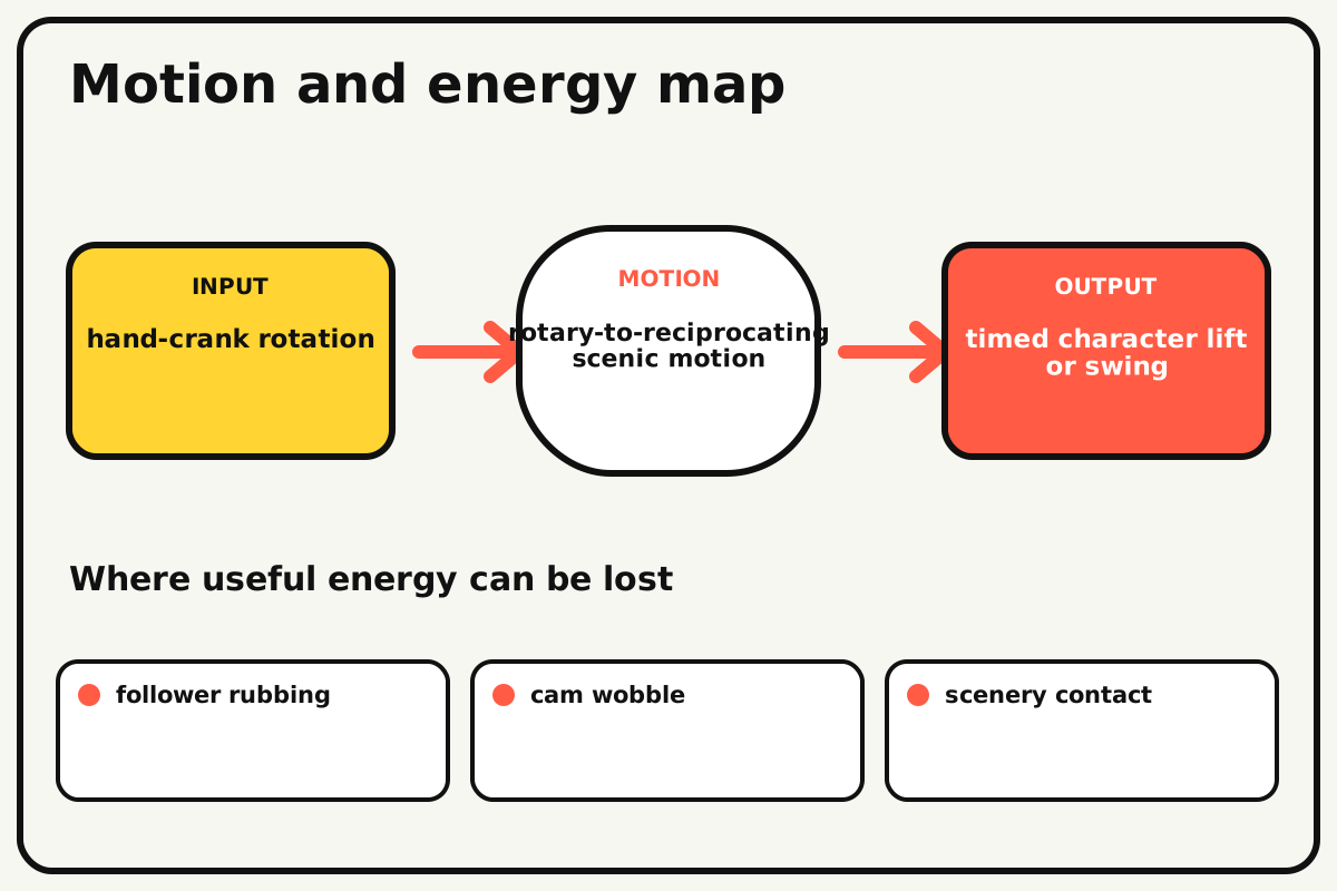
- Input
- hand-crank rotation
- Output
- timed character lift or swing
- Motion
- rotary-to-reciprocating scenic motion
- Energy losses
- follower rubbing, cam wobble, scenery contact, axle friction
Why this works
Mechanically programmed motion
The cam's changing radius acts like a physical timeline. The follower copies that radius as height, creating a repeatable motion sequence without electronics.
Look for: Mark the crank angle where the character begins rising, reaches the top, and returns.
Where the energy goes
Efficiency and losses
The ideal model leaves out follower rubbing, cam wobble, scenery contact, axle friction. These effects turn some input energy into heat, sound, vibration, or unwanted motion, so measured performance will be lower than an ideal calculation.
Look for: Run the build slowly and locate the first place where follower rubbing becomes visible or audible.
Math bite
Plan the dwell angle
Formula: dwell fraction = dwell angle / 360°
- High dwell angle = 90°
- Full cam turn = 360°
Substitute: fraction = 90/360 = 0.25
Result: The character stays near its high position for one quarter of each cycle.
At constant crank speed, angle fraction equals time fraction.
Hand speed may vary through the cycle.
Make it behave
Test, troubleshoot, and tune
Controlled test
Start here: Turn one cycle with the front panel open and scenery removed.
Success looks like: The follower stays on the cam and the character repeats its motion for ten turns.
Measure: High position, low position, and crank angles for rise and fall.
Change: the cam high-dwell angle
Keep constant: box, axle, follower, character mass, crank rate, and cam rise
- short dwell
- quarter-turn dwell
- long dwell
| Symptom | Likely cause | Confirm it | Fix |
|---|---|---|---|
| The follower jumps | Cam fall is too steep or crank too fast | Turn slowly through the falling section | Round the profile and reduce speed |
| The character tilts | Follower guide is short or figure off-center | Move without the cam | Lengthen guides and rebalance |
| The cam rubs a wall | Axle collars or cam center are wrong | View through the open front | Recenter with spacers |
| Motion changes each cycle | Cam slips on the axle | Align marks and apply light resistance | Strengthen the keyed cam hub |
Choose your tradeoff
Smooth transitions protect the follower and make motion readable. Larger cam rise gives dramatic movement but requires longer guides and more clearance; lightweight scenery reduces bending.
Keep experimenting
Try another version
Round eccentric
Start with a simple up-down circle cam.
Two characters
Add a second cam with a different phase.
Motion storyboard
Design cam angles from a four-panel animation timeline.
Build together
Classroom and access options
Classroom version
Teams can compare the cam high-dwell angle while keeping box, axle, follower, character mass, crank rate, and cam rise. Assign builder, tester, recorder, and explainer roles; have each team predict the result before collecting three trials.
Access adaptations
- Pre-cut repeated pieces and mark fold lines with high-contrast ink.
- Use large tabs, binder clips, and tape for easier one-handed assembly.
- Use a large crank, high-contrast character, and a follower that taps a paper sound strip at the top.
Reflect on the design
- How did the cam high-dwell angle change the measured result?
- Where did follower rubbing affect the build most strongly?
- What evidence shows that mechanically programmed motion explains the motion?
- Which change would improve timed character lift or swing without creating a new problem?
Glossary
- Mechanically programmed motion
- The cam's changing radius acts like a physical timeline.
- Input
- The action or energy supplied to a system; here it is hand-crank rotation.
- Output
- The useful response produced by a system; here it is timed character lift or swing.
- Efficiency
- The fraction of input energy that becomes useful output instead of friction, sound, heat, or unwanted motion.
Build your dreams
One build can start the next.
Share what you learned, change one variable, and help another builder understand what worked.
Explore more guidesSources and build notes
An original BrickLabClips cardboard machine with dimensionally specified construction.
- Cardboard design verification: Dimensions, fold allowances, repeated-motion joints, and likely load paths received an editorial geometry review.
Written and edited by BrickLabClips. Published 2026-07-22; updated 2026-07-22.