
- Difficulty
- Intermediate
- Build time
- 60-90 min
- Estimated cost
- $0-$18
- Age range
- 11-17
- Workspace
- A clear table about 90 cm wide
The finish line
What you will build
The guarded crank produces repeatable voltage above 2.5 V at the chosen speed and lights a protected LED without storing energy.
Learning goals
- Identify how slow hand-crank rotation produces low-voltage electrical energy.
- Construct and explain a rotary mechanical input-to-electrical output system.
- Measure how crank speed changes performance.
- Diagnose losses caused by bearing friction and gear friction.
Before you build
Materials, tools, and safety
Reuse-material cost: Usually under $5 with an existing kit. Supervision: Adult guidance recommended for wiring and cutting.
Tools
- Small screwdriver
- Wire stripper
- Multimeter
- Low-temperature glue gun or tape
Low-cost swaps
- Use alligator-clip leads for a no-solder version.
- Build and test the mechanism manually before adding electronics.
- Use a commercial classroom hand-crank generator module with enclosed gears.
Wiring table
| From | To | Purpose |
|---|---|---|
| Motor terminals | Bridge rectifier AC inputs | Accept either crank direction |
| Rectifier positive | 220 Ω resistor then LED anode | Limit indicator current |
| LED cathode | Rectifier negative | Complete load circuit |
| Multimeter | Across rectifier output | Measure generated DC voltage |
Project-specific safety
- Use only the listed low-voltage battery supply; never use mains electricity.
- Disconnect power before changing wires and stop if a motor, wire, or battery becomes warm.
- Crank by hand at low speed, guard gears, use no batteries or mains connection, never spin with a drill, and stop if parts loosen or warm.
Orient the build
Place the build so slow hand-crank rotation is on your left and low-voltage electrical energy is on your right. Call the side facing you the front, the far side the back, the tabletop the bottom, and the opposite face the top.
Build it
Step-by-step instructions
Step 1
Build the base
Clamp the motor and crank shafts on a wide braced platform.
Support both sides of each shaft.
Step 2
Add speed increase
Connect a large hand pulley or gear to a smaller motor pulley.
Align the transmission and add guards.
Step 3
Test rotation by hand
Turn slowly with no wires connected.
Listen for rubbing and inspect guards.
Builder checkpoint: After test rotation by hand, the first subassembly should stay aligned when handled gently.
Step 4
Build the rectifier output
Connect motor to bridge AC inputs and LED plus resistor to DC outputs.
Verify diode markings.
Watch for: If this stage binds or drifts, inspect diode voltage drop before adding more parts.
Step 5
Measure open circuit
Connect the multimeter and turn at three counted crank rates.
Record voltage and polarity.
Step 6
Connect the LED load
Crank slowly until the LED becomes visible.
Do not bypass the resistor.
Builder checkpoint: After connect the led load, operate the build slowly and confirm that low-voltage electrical energy begins without binding.
Step 7
Compare effort
At the same speed, compare with LED connected and disconnected.
Describe the felt torque difference.
Step 8
Run repeated trials
Count ten crank turns in a fixed time and record voltage three times.
Stop and inspect mounts.
Builder checkpoint: At the final checkpoint, The guarded crank produces repeatable voltage above 2.5 V at the chosen speed and lights a protected LED without storing energy.
See the engineering
Why it works
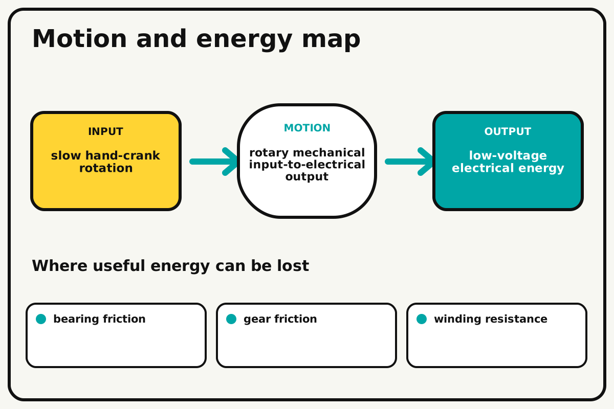
- Input
- slow hand-crank rotation
- Output
- low-voltage electrical energy
- Motion
- rotary mechanical input-to-electrical output
- Energy losses
- bearing friction, gear friction, winding resistance, diode voltage drop
Why this works
Motor as generator
Turning the shaft moves motor coils through a magnetic field, inducing a voltage. Faster rotation usually raises open-circuit voltage, while a connected load makes cranking harder.
Look for: Measure polarity while turning clockwise and counterclockwise, then compare effort with the LED disconnected and connected.
Where the energy goes
Efficiency and losses
The ideal model leaves out bearing friction, gear friction, winding resistance, diode voltage drop. These effects turn some input energy into heat, sound, vibration, or unwanted motion, so measured performance will be lower than an ideal calculation.
Look for: Run the build slowly and locate the first place where bearing friction becomes visible or audible.
Math bite
Calculate ideal gear speed
Formula: motor speed = crank speed × large pulley diameter / small pulley diameter
- Crank = 60 rpm
- Large = 9 cm
- Small = 3 cm
Substitute: motor speed = 60 × 9 / 3 = 180 rpm
Result: The motor turns about 180 rpm ideally.
Faster motor rotation usually produces more voltage.
Belt slip and hand-speed variation reduce accuracy.
Make it behave
Test, troubleshoot, and tune
Controlled test
Start here: Turn the guarded motor slowly with the LED disconnected and measure voltage first.
Success looks like: The system exceeds 2.5 V at the chosen rate and lights the protected LED repeatably.
Measure: Crank rate, voltage, LED state, effort, and temperature.
Change: crank speed
Keep constant: generator, gearing, rectifier, resistor, meter, and operator
- 30 rpm
- 45 rpm
- 60 rpm
| Symptom | Likely cause | Confirm it | Fix |
|---|---|---|---|
| Voltage stays near zero | Meter range, motor, or connection is wrong | Measure directly at motor terminals | Correct meter and wiring |
| LED never lights | Rectifier polarity or voltage is insufficient | Measure DC output while cranking | Correct bridge output or increase safe speed |
| Crank slips | Belt tension or gear alignment is poor | Mark both shafts | Align and adjust moderate tension |
| Mount vibrates | Shaft support or base is weak | Turn slowly and watch frame | Brace and add a second bearing support |
Choose your tradeoff
Reduce mechanical friction before increasing speed. Higher speed raises voltage but also increases guarding needs, noise, and bearing load.
Keep experimenting
Try another version
Meter-only generator
Measure voltage without an LED.
Voltage-speed graph
Plot average voltage against crank rate.
Load comparison
Compare current through two safe resistor values without charging a battery.
Build together
Classroom and access options
Classroom version
Teams can compare crank speed while keeping generator, gearing, rectifier, resistor, meter, and operator. Assign builder, tester, recorder, and explainer roles; have each team predict the result before collecting three trials.
Access adaptations
- Color-code and label every wire at both ends.
- Use clip leads, larger controls, and pre-crimped connectors when fine motor work is difficult.
- Use a broad crank handle and an optional partner role for holding the base and reading the meter.
Reflect on the design
- How did crank speed change the measured result?
- Where did bearing friction affect the build most strongly?
- What evidence shows that motor as generator explains the motion?
- Which change would improve low-voltage electrical energy without creating a new problem?
Glossary
- Motor as generator
- Turning the shaft moves motor coils through a magnetic field, inducing a voltage.
- Input
- The action or energy supplied to a system; here it is slow hand-crank rotation.
- Output
- The useful response produced by a system; here it is low-voltage electrical energy.
- Efficiency
- The fraction of input energy that becomes useful output instead of friction, sound, heat, or unwanted motion.
Build your dreams
One build can start the next.
Share what you learned, change one variable, and help another builder understand what worked.
Explore more guidesSources and build notes
A platform-agnostic low-voltage robotics or electronics project with original assembly guidance.
- Low-voltage design review: Battery voltage, polarity, component roles, current paths, and motor or LED protection were editorially checked.
Written and edited by BrickLabClips. Published 2026-07-22; updated 2026-07-22.
Next builds
Related guides
Cardboard Wind Turbine
Build a guarded tabletop rotor and compare blade angle, area, and load using a household fan as a repeatable wind source.
Robotics/electronicsConductivity Tester
Use a current-limited LED probe to compare whether common dry materials complete a low-voltage circuit.
Simple Motorized Fan
Build a guarded low-voltage fan, switch it with a transistor, and compare airflow at two safe blade pitches.