
- Difficulty
- Advanced
- Build time
- 130-200 min
- Estimated cost
- $0-$45
- Age range
- 13-18
- Workspace
- A clear table about 90 cm wide
The finish line
What you will build
The robot turns toward a diffuse stationary light from three starting headings and stops within 30 cm in four of five trials.
Learning goals
- Identify how left and right light-sensor readings produces steering toward higher light intensity.
- Construct and explain a light gradient-to-differential wheel motion system.
- Measure how sensor divider depth changes performance.
- Diagnose losses caused by ambient light and sensor mismatch.
Before you build
Materials, tools, and safety
Reuse-material cost: Usually under $5 with an existing kit. Supervision: Adult guidance recommended for wiring and cutting.
Tools
- Small screwdriver
- Wire stripper
- Multimeter
- Low-temperature glue gun or tape
Low-cost swaps
- Use alligator-clip leads for a no-solder version.
- Build and test the mechanism manually before adding electronics.
- Mount the paired sensors on a hand-held pointer and display direction before building a rover.
Wiring table
| From | To | Purpose |
|---|---|---|
| Light sensor outputs | Analog A0 and A1 | Measure left and right brightness |
| Sensor power | Rated controller VCC and GND | Supply matched sensor dividers |
| Controller PWM/direction | Dual H-bridge inputs | Set differential motor motion |
| Motor battery | H-bridge supply | Power motors separately |
| All grounds | Common ground | Share voltage reference |
Project-specific safety
- Use only the listed low-voltage battery supply; never use mains electricity.
- Disconnect power before changing wires and stop if a motor, wire, or battery becomes warm.
- Use low-voltage power and a normal diffused flashlight; never use lasers or stare into high-intensity LEDs.
Orient the build
Place the build so left and right light-sensor readings is on your left and steering toward higher light intensity is on your right. Call the side facing you the front, the far side the back, the tabletop the bottom, and the opposite face the top.
Build it
Step-by-step instructions
Step 1
Build and align the rover
Match wheels and confirm straight unpowered rolling.
Keep the front deck clear.
Step 2
Mount paired sensors
Place sensors side by side with an opaque divider centered between them.
Aim both level and forward.
Step 3
Wire sensors and driver
Use rated sensor voltage, H-bridge motor power, and common ground.
Label left and right channels.
Builder checkpoint: After wire sensors and driver, the first subassembly should stay aligned when handled gently.
Step 4
Calibrate darkness
Record each sensor under even room light and under the target at equal distance.
Normalize mismatched ranges.
Watch for: If this stage binds or drifts, inspect motor mismatch before adding more parts.
Step 5
Test direction readings
Rotate the robot through left, center, and right positions with motors off.
Confirm the expected sign of error.
Step 6
Run wheels raised
Command slow left and right corrections from a moved flashlight.
Verify steering direction.
Builder checkpoint: After run wheels raised, operate the build slowly and confirm that steering toward higher light intensity begins without binding.
Step 7
Add stop behavior
Use average brightness or an ultrasonic limit to stop near the source.
Start with a conservative threshold.
Step 8
Run three-heading trials
Begin left, right, and backward from the same radius.
Record approach, final distance, and false turns.
Builder checkpoint: At the final checkpoint, The robot turns toward a diffuse stationary light from three starting headings and stops within 30 cm in four of five trials.
See the engineering
Why it works
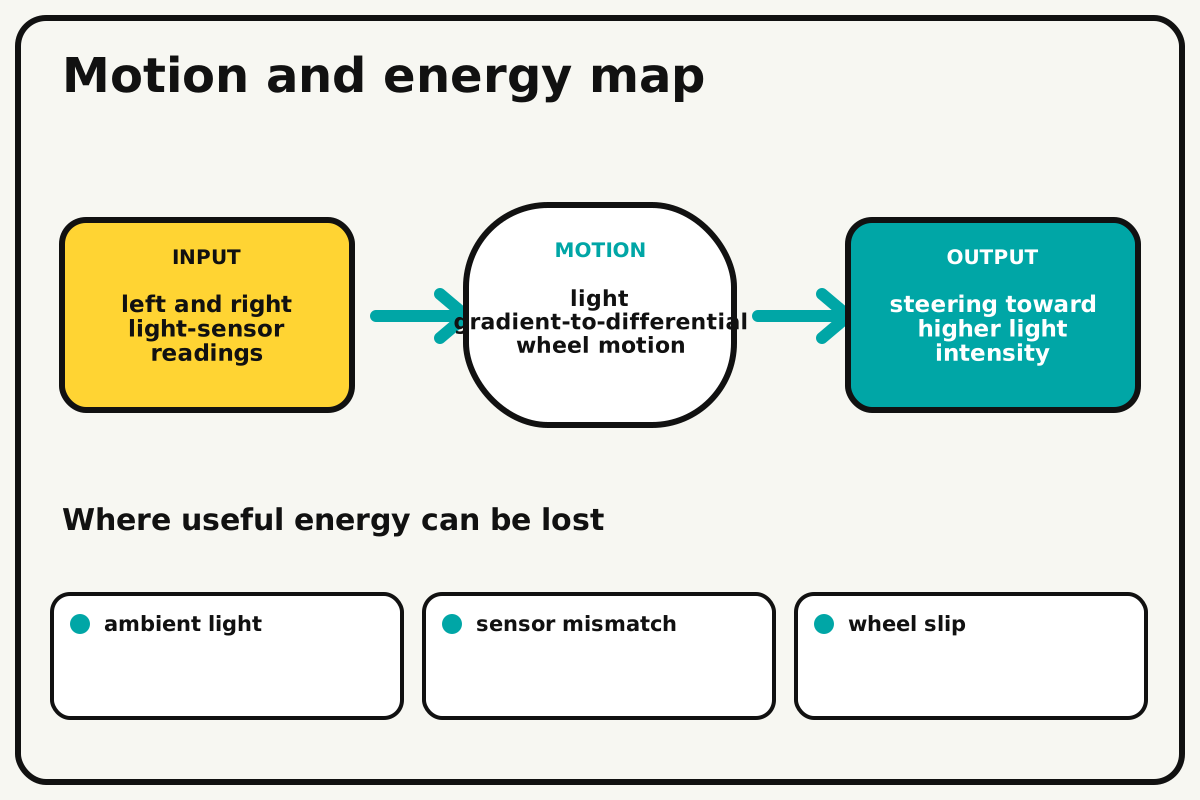
- Input
- left and right light-sensor readings
- Output
- steering toward higher light intensity
- Motion
- light gradient-to-differential wheel motion
- Energy losses
- ambient light, sensor mismatch, wheel slip, motor mismatch
Why this works
Differential light sensing
A divider creates a small shadow difference between paired sensors. The controller uses their normalized difference to steer toward the brighter side.
Look for: Rotate the unpowered robot in place and graph both sensor values before enabling motors.
Where the energy goes
Efficiency and losses
The ideal model leaves out ambient light, sensor mismatch, wheel slip, motor mismatch. These effects turn some input energy into heat, sound, vibration, or unwanted motion, so measured performance will be lower than an ideal calculation.
Look for: Run the build slowly and locate the first place where ambient light becomes visible or audible.
Math bite
Calculate directional error
Formula: error = normalized left - normalized right
- Left = 0.75
- Right = 0.45
Substitute: error = 0.75 - 0.45 = 0.30
Result: A positive 0.30 error commands a leftward correction.
Larger error can produce a stronger turn.
Reflections and sensor mismatch affect the reading.light_seeker.ino
A complete normalized two-sensor steering loop with a measured stop threshold.
const int leftLight=A0, rightLight=A1;
const int leftPwm=5, rightPwm=6, leftDir=7, rightDir=8;
const int baseSpeed=95, stopLevel=850;
void setup(){
  pinMode(leftPwm,OUTPUT); pinMode(rightPwm,OUTPUT);
  pinMode(leftDir,OUTPUT); pinMode(rightDir,OUTPUT);
  digitalWrite(leftDir,HIGH); digitalWrite(rightDir,HIGH);
}
void loop(){
  int left=analogRead(leftLight), right=analogRead(rightLight);
  int average=(left+right)/2;
  if(average>stopLevel){ analogWrite(leftPwm,0); analogWrite(rightPwm,0); return; }
  int correction=constrain((left-right)/3,-70,70);
  analogWrite(leftPwm,constrain(baseSpeed-correction,0,180));
  analogWrite(rightPwm,constrain(baseSpeed+correction,0,180));
  delay(15);
}
Make it behave
Test, troubleshoot, and tune
Controlled test
Start here: Rotate the unpowered robot while logging both sensor values.
Success looks like: The robot approaches the diffuse target from three headings and stops within 30 cm in four of five runs.
Measure: Direction error, approach time, final distance, and false turns.
Change: sensor divider depth
Keep constant: robot, room, target brightness, starting radius, speed, and battery
- 2 cm divider
- 4 cm divider
- 6 cm divider
| Symptom | Likely cause | Confirm it | Fix |
|---|---|---|---|
| It turns away | Sensor labels or motor correction sign is reversed | Move light to one side with wheels raised | Swap mapping in code |
| It oscillates | Gain is high or sensors are too sensitive | Test from directly ahead | Reduce gain and average samples |
| It follows room reflections | Target contrast is low | Map readings with target off | Dim stray light and use a diffuser |
| It never stops | Threshold is unreachable or sensors saturate | Read values at 30 cm | Set threshold from measured data |
Choose your tradeoff
Improve sensor matching and shielding before raising steering gain. A deeper divider gives stronger direction contrast but creates a blind zone when the target is centered.
Keep experimenting
Try another version
Stationary pointer
Use LEDs to show brighter side.
Fast approach
Minimize time without overshoot.
Search state
Rotate slowly when both sensors are below a measured threshold.
Build together
Classroom and access options
Classroom version
Teams can compare sensor divider depth while keeping robot, room, target brightness, starting radius, speed, and battery. Assign builder, tester, recorder, and explainer roles; have each team predict the result before collecting three trials.
Access adaptations
- Color-code and label every wire at both ends.
- Use clip leads, larger controls, and pre-crimped connectors when fine motor work is difficult.
- Use audible left/right indicators during calibration and high-contrast sensor labels.
Reflect on the design
- How did sensor divider depth change the measured result?
- Where did ambient light affect the build most strongly?
- What evidence shows that differential light sensing explains the motion?
- Which change would improve steering toward higher light intensity without creating a new problem?
Glossary
- Differential light sensing
- A divider creates a small shadow difference between paired sensors.
- Input
- The action or energy supplied to a system; here it is left and right light-sensor readings.
- Output
- The useful response produced by a system; here it is steering toward higher light intensity.
- Efficiency
- The fraction of input energy that becomes useful output instead of friction, sound, heat, or unwanted motion.
Build your dreams
One build can start the next.
Share what you learned, change one variable, and help another builder understand what worked.
Explore more guidesSources and build notes
A platform-agnostic low-voltage robotics or electronics project with original assembly guidance.
- Low-voltage design review: Battery voltage, polarity, component roles, current paths, and motor or LED protection were editorially checked.
Written and edited by BrickLabClips. Published 2026-07-22; updated 2026-07-22.