
- Difficulty
- Beginner
- Build time
- 45-70 min
- Estimated cost
- $0-$10
- Age range
- 11-16
- Workspace
- A clear table about 90 cm wide
The finish line
What you will build
The LED turns on below a measured light threshold, stays off in bright conditions, and avoids rapid flicker near the boundary.
Learning goals
- Identify how light-dependent sensor resistance produces controlled LED illumination.
- Construct and explain a light level-to-electrical switching system.
- Measure how threshold gap changes performance.
- Diagnose losses caused by ambient reflections and sensor tolerance.
Before you build
Materials, tools, and safety
Reuse-material cost: $0-$3 with reused materials. Supervision: Adult guidance recommended for wiring and cutting.
Tools
- Small screwdriver
- Wire stripper
- Multimeter
- Low-temperature glue gun or tape
Low-cost swaps
- Use alligator-clip leads for a no-solder version.
- Build and test the mechanism manually before adding electronics.
- Use an LED night-light module designed for 3-5 V and study its threshold without modifying mains products.
Wiring table
| From | To | Purpose |
|---|---|---|
| 5 V | Photoresistor | Feed top of sensor divider |
| Photoresistor/fixed-resistor midpoint | Analog A0 | Measure light-dependent voltage |
| 10 kΩ resistor | Midpoint and GND | Complete divider |
| Pin 9 | LED anode through 220 Ω | Drive current-limited light |
| LED cathode | GND | Complete LED circuit |
Project-specific safety
- Use only the listed low-voltage battery supply; never use mains electricity.
- Disconnect power before changing wires and stop if a motor, wire, or battery becomes warm.
- Use only battery or USB low voltage; do not open or modify a wall-powered night light.
Orient the build
Place the build so light-dependent sensor resistance is on your left and controlled LED illumination is on your right. Call the side facing you the front, the far side the back, the tabletop the bottom, and the opposite face the top.
Build it
Step-by-step instructions
Step 1
Build the divider
Connect photoresistor to 5 V, fixed resistor to ground, and midpoint to A0.
Keep leads apart.
Step 2
Add the indicator
Connect pin 9 through 220 Ω to LED anode and cathode to ground.
Verify polarity.
Step 3
Read raw values
Print A0 in bright room, under a paper shade, and in a dark box.
Record ranges.
Builder checkpoint: After read raw values, the first subassembly should stay aligned when handled gently.
Step 4
Choose thresholds
Set an on threshold between dark and bright readings and an off threshold farther toward bright.
Keep on and off values distinct.
Watch for: If this stage binds or drifts, inspect threshold chatter before adding more parts.
Step 5
Program the state
If dark crosses on threshold, light LED; if bright crosses off threshold, turn it off.
Retain state between thresholds.
Step 6
Shield the sensor
Add a short paper hood so the LED does not shine directly on its own sensor.
Keep the opening visible.
Builder checkpoint: After shield the sensor, operate the build slowly and confirm that controlled LED illumination begins without binding.
Step 7
Run transition trials
Cover and uncover gradually ten times.
Record flicker and switching values.
Step 8
Tune placement
Move the sensor or adjust thresholds for the intended room.
Document the final readings.
Builder checkpoint: At the final checkpoint, The LED turns on below a measured light threshold, stays off in bright conditions, and avoids rapid flicker near the boundary.
See the engineering
Why it works
- Input
- light-dependent sensor resistance
- Output
- controlled LED illumination
- Motion
- light level-to-electrical switching
- Energy losses
- ambient reflections, sensor tolerance, battery drop, threshold chatter
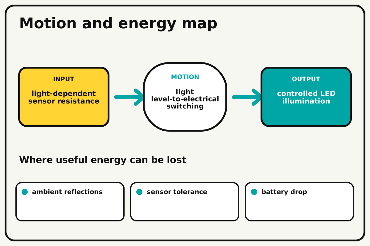
Why this works
Light threshold control
A photoresistor and fixed resistor divide battery voltage. The measured midpoint changes with light, and code or a transistor threshold decides when the LED turns on.
Look for: Shade the sensor gradually and record the value where the LED switches on and where it switches off.
Where the energy goes
Efficiency and losses
The ideal model leaves out ambient reflections, sensor tolerance, battery drop, threshold chatter. These effects turn some input energy into heat, sound, vibration, or unwanted motion, so measured performance will be lower than an ideal calculation.
Look for: Run the build slowly and locate the first place where ambient reflections becomes visible or audible.
Math bite
Calculate divider voltage
Formula: Vout = Vin × fixed resistance / (sensor + fixed)
- Vin = 5 V
- Sensor = 30 kΩ
- Fixed = 10 kΩ
Substitute: Vout = 5 × 10 / (30 + 10) = 1.25 V
Result: The divider midpoint is about 1.25 volts for this sensor resistance.
Sensor orientation determines whether darkness raises or lowers the reading.
Photoresistor tolerance is broad.night_light.ino
A complete threshold controller with sample averaging and hysteresis.
const int sensorPin=A0, ledPin=9;
const int darkOn=360, brightOff=440; bool lightOn=false;
void setup(){ pinMode(ledPin,OUTPUT); Serial.begin(9600); }
void loop(){
  long total=0; for(int i=0;i<10;i++){ total+=analogRead(sensorPin); delay(3); }
  int reading=total/10;
  if(!lightOn && reading<darkOn) lightOn=true;
  else if(lightOn && reading>brightOff) lightOn=false;
  analogWrite(ledPin,lightOn?180:0);
  Serial.println(reading); delay(40);
}
Make it behave
Test, troubleshoot, and tune
Controlled test
Start here: Verify bright and shaded analog ranges before enabling automatic output.
Success looks like: Ten light transitions switch correctly without rapid flicker at the boundary.
Measure: Analog reading, switch state, on threshold, off threshold, and flicker count.
Change: threshold gap
Keep constant: sensor, divider, LED, room, hood, and sample rate
- small gap
- medium gap
- large gap
| Symptom | Likely cause | Confirm it | Fix |
|---|---|---|---|
| LED behaves backward | Divider orientation or comparison sign is reversed | Print values bright and dark | Invert code logic or swap divider order |
| It flickers near threshold | No hysteresis or readings are noisy | Hold light near the boundary | Separate on/off thresholds and average samples |
| It never gets dark enough | LED feeds the sensor or threshold is wrong | Cover sensor fully and read value | Add hood and recalibrate |
| LED does not light | Polarity, resistor, or pin is wrong | Run a direct LED test | Correct with power off |
Choose your tradeoff
Use measured room values and hysteresis before adding delay. A wide threshold gap prevents flicker but requires a larger change in light to switch back.
Keep experimenting
Try another version
Manual sensor graph
Print readings without controlling an LED.
Brightness control
Map darkness to PWM level.
Adaptive baseline
Measure room light at startup and set relative thresholds.
Build together
Classroom and access options
Classroom version
Teams can compare threshold gap while keeping sensor, divider, led, room, hood, and sample rate. Assign builder, tester, recorder, and explainer roles; have each team predict the result before collecting three trials.
Access adaptations
- Color-code and label every wire at both ends.
- Use clip leads, larger controls, and pre-crimped connectors when fine motor work is difficult.
- Add a large threshold knob and a tactile hood over the sensor for controlled shading.
Reflect on the design
- How did threshold gap change the measured result?
- Where did ambient reflections affect the build most strongly?
- What evidence shows that light threshold control explains the motion?
- Which change would improve controlled LED illumination without creating a new problem?
Glossary
- Light threshold control
- A photoresistor and fixed resistor divide battery voltage.
- Input
- The action or energy supplied to a system; here it is light-dependent sensor resistance.
- Output
- The useful response produced by a system; here it is controlled LED illumination.
- Efficiency
- The fraction of input energy that becomes useful output instead of friction, sound, heat, or unwanted motion.
Build your dreams
One build can start the next.
Share what you learned, change one variable, and help another builder understand what worked.
Explore more guidesSources and build notes
A platform-agnostic low-voltage robotics or electronics project with original assembly guidance.
- Low-voltage design review: Battery voltage, polarity, component roles, current paths, and motor or LED protection were editorially checked.
Written and edited by BrickLabClips. Published 2026-07-22; updated 2026-07-22.