
- Difficulty
- Beginner
- Build time
- 40-60 min
- Estimated cost
- $0-$10
- Age range
- 11-16
- Workspace
- A clear table about 90 cm wide
The finish line
What you will build
The alarm remains silent while level and sounds in nine of ten trials when the platform tilts past the calibrated angle.
Learning goals
- Identify how tilt-switch contact changing with orientation produces audible buzzer signal.
- Construct and explain a angular tilt-to-electrical state change system.
- Measure how sensor mounting angle changes performance.
- Diagnose losses caused by contact bounce and mount movement.
Before you build
Materials, tools, and safety
Reuse-material cost: $0-$3 with reused materials. Supervision: Adult guidance recommended for wiring and cutting.
Tools
- Small screwdriver
- Wire stripper
- Multimeter
- Low-temperature glue gun or tape
Low-cost swaps
- Use alligator-clip leads for a no-solder version.
- Build and test the mechanism manually before adding electronics.
- Use an LED and resistor as a silent indicator during classroom testing.
Wiring table
| From | To | Purpose |
|---|---|---|
| Battery +4.5 V | Buzzer positive | Supply rated buzzer voltage |
| Buzzer negative | Transistor collector or drain | Switch buzzer current |
| Transistor emitter or source | Battery negative | Complete return path |
| Tilt switch through 1 kΩ | Transistor control and battery positive | Command alarm state |
| 10 kΩ resistor | Control node and ground | Keep alarm off when switch is open |
Project-specific safety
- Use only the listed low-voltage battery supply; never use mains electricity.
- Disconnect power before changing wires and stop if a motor, wire, or battery becomes warm.
- Use low voltage, keep buzzer volume comfortable, disconnect power before remounting, and secure small sensor parts inside a case.
Orient the build
Place the build so tilt-switch contact changing with orientation is on your left and audible buzzer signal is on your right. Call the side facing you the front, the far side the back, the tabletop the bottom, and the opposite face the top.
Build it
Step-by-step instructions
Step 1
Characterize the switch
Use continuity mode with no battery and rotate the switch through 180 degrees.
Mark open and closed orientations.
Step 2
Build the mounting wedge
Make an adjustable card bracket with angle marks every 10 degrees.
Hold the sensor without crushing its leads.
Step 3
Wire the buzzer stage
Connect buzzer positive to battery positive and negative to transistor output.
Keep power off.
Builder checkpoint: After wire the buzzer stage, the first subassembly should stay aligned when handled gently.
Step 4
Add the sensor control
Wire tilt switch through the resistor to the transistor control and add pull-down.
Insulate joints.
Watch for: If this stage binds or drifts, inspect threshold hysteresis before adding more parts.
Step 5
Test on a breadboard
Power briefly and rotate the sensor by hand.
Confirm on and off states.
Step 6
Mount the circuit
Secure battery, buzzer, and board to a wide model platform.
Add strain relief.
Builder checkpoint: After mount the circuit, operate the build slowly and confirm that audible buzzer signal begins without binding.
Step 7
Calibrate threshold
Set the wedge so the alarm changes near the chosen angle.
Measure with a paper protractor.
Step 8
Run ten trials
Return level between tests and approach from the same direction.
Record trigger angle and misses.
Builder checkpoint: At the final checkpoint, The alarm remains silent while level and sounds in nine of ten trials when the platform tilts past the calibrated angle.
See the engineering
Why it works
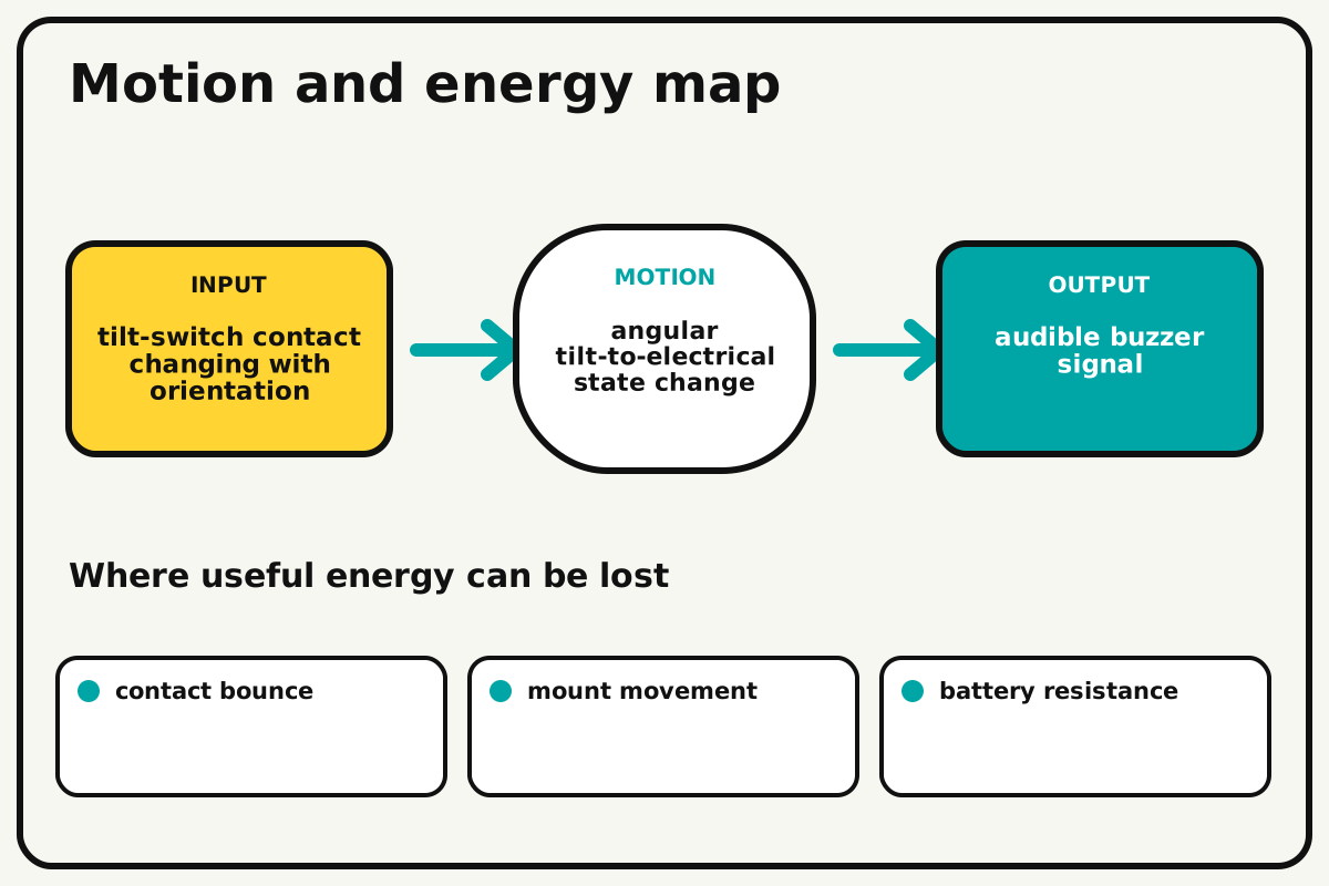
- Input
- tilt-switch contact changing with orientation
- Output
- audible buzzer signal
- Motion
- angular tilt-to-electrical state change
- Energy losses
- contact bounce, mount movement, battery resistance, threshold hysteresis
Why this works
Gravity-referenced switching
The tilt sensor closes or opens when its internal conductor moves under gravity. A transistor lets the small sensor current control a buzzer without overloading the switch.
Look for: Tilt the unpowered sensor slowly and use continuity mode to find the angle where its state changes.
Where the energy goes
Efficiency and losses
The ideal model leaves out contact bounce, mount movement, battery resistance, threshold hysteresis. These effects turn some input energy into heat, sound, vibration, or unwanted motion, so measured performance will be lower than an ideal calculation.
Look for: Run the build slowly and locate the first place where contact bounce becomes visible or audible.
Math bite
Calculate alarm reliability
Formula: reliability = successful alarms / tilt trials × 100%
- Successful alarms = 9
- Trials = 10
Substitute: reliability = 9 / 10 × 100% = 90%
Result: The alarm triggers on 90 percent of test tilts.
A larger sample gives better confidence.
Contact bounce and hand angle introduce variation.
Make it behave
Test, troubleshoot, and tune
Controlled test
Start here: Test the transistor and buzzer by applying the control signal directly before adding the tilt switch.
Success looks like: The device stays silent level and alarms in nine of ten threshold trials.
Measure: Trigger angle, response delay, missed alarms, and false alarms.
Change: sensor mounting angle
Keep constant: circuit, battery, platform, tilt rate, direction, and reset
- 20° mount
- 30° mount
- 40° mount
| Symptom | Likely cause | Confirm it | Fix |
|---|---|---|---|
| Alarm is always on | Switch orientation or pull-down is wrong | Disconnect the switch and inspect control voltage | Rotate sensor or fix pull-down |
| Buzzer is weak | Voltage is low or transistor is miswired | Measure battery under load | Correct pins and replace cells |
| Trigger varies widely | Mount is loose or switch bounces | Hold the bracket and repeat slowly | Stiffen mount and add debounce delay if coded |
| Alarm fails after tilting | Battery or lead shifts | Shake gently with power off | Add mechanical restraint and strain relief |
Choose your tradeoff
Calibrate mounting angle before changing electronics. A sensitive angle gives early warning but can increase false alarms from vibration and small table movement.
Keep experimenting
Try another version
LED tilt indicator
Use only an LED and resistor.
Latch circuit
Keep the alarm on until a reset button is pressed.
Angle sensor
Replace the switch with an accelerometer and compare continuous readings.
Build together
Classroom and access options
Classroom version
Teams can compare sensor mounting angle while keeping circuit, battery, platform, tilt rate, direction, and reset. Assign builder, tester, recorder, and explainer roles; have each team predict the result before collecting three trials.
Access adaptations
- Color-code and label every wire at both ends.
- Use clip leads, larger controls, and pre-crimped connectors when fine motor work is difficult.
- Add a bright LED in parallel with its own resistor and use a large power switch.
Reflect on the design
- How did sensor mounting angle change the measured result?
- Where did contact bounce affect the build most strongly?
- What evidence shows that gravity-referenced switching explains the motion?
- Which change would improve audible buzzer signal without creating a new problem?
Glossary
- Gravity-referenced switching
- The tilt sensor closes or opens when its internal conductor moves under gravity.
- Input
- The action or energy supplied to a system; here it is tilt-switch contact changing with orientation.
- Output
- The useful response produced by a system; here it is audible buzzer signal.
- Efficiency
- The fraction of input energy that becomes useful output instead of friction, sound, heat, or unwanted motion.
Build your dreams
One build can start the next.
Share what you learned, change one variable, and help another builder understand what worked.
Explore more guidesSources and build notes
A platform-agnostic low-voltage robotics or electronics project with original assembly guidance.
- Low-voltage design review: Battery voltage, polarity, component roles, current paths, and motor or LED protection were editorially checked.
Written and edited by BrickLabClips. Published 2026-07-22; updated 2026-07-22.