
- Difficulty
- Intermediate
- Build time
- 70-110 min
- Estimated cost
- $0-$15
- Age range
- 12-17
- Workspace
- A clear table about 90 cm wide
The finish line
What you will build
The switched electromagnet lifts at least five steel paper clips for five seconds and remains cool during duty-cycled testing.
Learning goals
- Identify how brief low-voltage current through a wire coil produces temporary magnetic attraction.
- Construct and explain a electrical current-to-steel-object lift system.
- Measure how coil turn count changes performance.
- Diagnose losses caused by wire resistance and air gap.
Before you build
Materials, tools, and safety
Reuse-material cost: Usually under $5 with an existing kit. Supervision: Adult guidance recommended for wiring and cutting.
Tools
- Small screwdriver
- Wire stripper
- Multimeter
- Low-temperature glue gun or tape
Low-cost swaps
- Use alligator-clip leads for a no-solder version.
- Build and test the mechanism manually before adding electronics.
- Use a commercial low-voltage electromagnet module with a documented current rating.
Wiring table
| From | To | Purpose |
|---|---|---|
| Battery +4.5 V | Coil input | Supply low-voltage coil current |
| Coil output | MOSFET drain | Switch coil return |
| MOSFET source | Battery negative | Complete current path |
| Flyback diode | Across coil, stripe to positive | Clamp turn-off voltage |
| Button and 10 kΩ pull-down | MOSFET gate | Create momentary on command |
Project-specific safety
- Use only the listed low-voltage battery supply; never use mains electricity.
- Disconnect power before changing wires and stop if a motor, wire, or battery becomes warm.
- Use momentary five-second power only, disconnect if coil or battery warms, never connect to mains, keep away from medical devices, and do not lift sharp or heavy objects.
Orient the build
Place the build so brief low-voltage current through a wire coil is on your left and temporary magnetic attraction is on your right. Call the side facing you the front, the far side the back, the tabletop the bottom, and the opposite face the top.
Build it
Step-by-step instructions
Step 1
Prepare the core
Inspect and smooth the bolt and wrap one paper insulation layer around its shaft.
Leave ends exposed.
Step 2
Wind the coil
Wrap 80-120 neat turns in one direction, leaving 10 cm leads.
Tape layers so they cannot unwind.
Step 3
Expose wire ends
Have an adult scrape enamel from the last 1 cm of each lead.
Confirm continuity with a multimeter.
Builder checkpoint: After expose wire ends, the first subassembly should stay aligned when handled gently.
Step 4
Measure coil resistance
Record resistance before connecting power.
Calculate expected current and stop if it exceeds component ratings.
Watch for: If this stage binds or drifts, inspect heat before adding more parts.
Step 5
Wire the MOSFET stage
Connect battery, coil, transistor, flyback diode, button, and pull-down.
Verify diode stripe at positive.
Step 6
Run a one-second test
Press briefly and pick up one clip.
Release and confirm the field disappears.
Builder checkpoint: After run a one-second test, operate the build slowly and confirm that temporary magnetic attraction begins without binding.
Step 7
Set a safe duty cycle
Use at most five seconds on followed by sixty seconds off.
Check temperature after power is disconnected.
Step 8
Compare coil turns
Test equal-time lifts with two prepared coils or taps.
Record clip count and current.
Builder checkpoint: At the final checkpoint, The switched electromagnet lifts at least five steel paper clips for five seconds and remains cool during duty-cycled testing.
See the engineering
Why it works
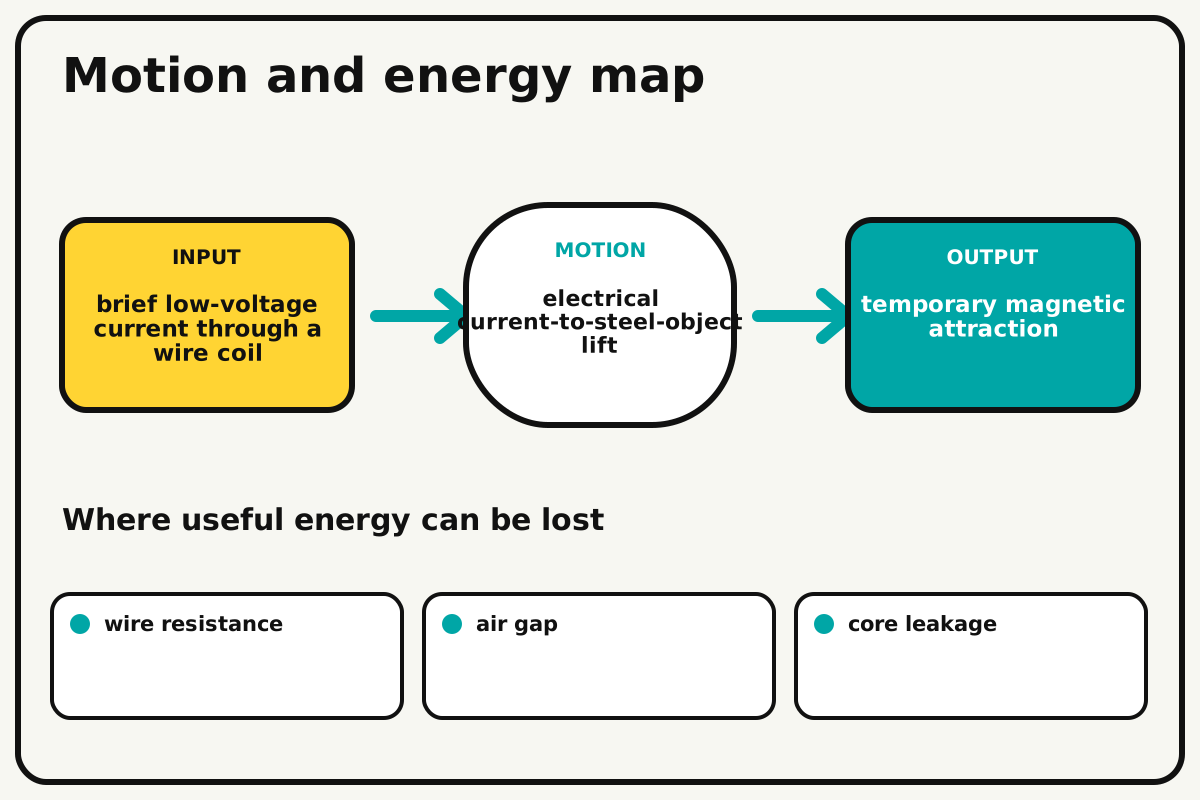
- Input
- brief low-voltage current through a wire coil
- Output
- temporary magnetic attraction
- Motion
- electrical current-to-steel-object lift
- Energy losses
- wire resistance, air gap, core leakage, heat
Why this works
Current-generated magnetic field
Each coil turn adds magnetic field in the same direction around the iron core. More turns or current can strengthen the field, but resistance and heating impose safe limits.
Look for: Count lifted paper clips after equal five-second on periods and one-minute cooling periods.
Where the energy goes
Efficiency and losses
The ideal model leaves out wire resistance, air gap, core leakage, heat. These effects turn some input energy into heat, sound, vibration, or unwanted motion, so measured performance will be lower than an ideal calculation.
Look for: Run the build slowly and locate the first place where wire resistance becomes visible or audible.
Math bite
Estimate coil current
Formula: current = voltage / resistance
- Voltage = 4.5 V
- Coil resistance = 15 Ω
Substitute: current = 4.5 / 15 = 0.30 A
Result: The ideal current is about 0.30 amperes.
Choose a transistor, diode, wire, and battery rated above this current.
Battery resistance and coil heating lower current over time.
Make it behave
Test, troubleshoot, and tune
Controlled test
Start here: Measure coil resistance and calculate expected current before applying power.
Success looks like: The lifter holds five clips for five seconds and stays cool under the duty cycle.
Measure: Clip count, current, on-time, coil temperature after power-off, and release behavior.
Change: coil turn count
Keep constant: core, wire gauge, voltage, duty cycle, clips, and air gap
- 80 turns
- 100 turns
- 120 turns
| Symptom | Likely cause | Confirm it | Fix |
|---|---|---|---|
| Nothing lifts | Enamel remains or circuit is open | Measure continuity | Rescrape and reconnect with power off |
| Transistor warms | Current exceeds rating or gate is not fully on | Measure coil resistance and current | Use a rated logic MOSFET and reduce duty |
| Clips remain after release | Core retains magnetism | Remove power and tap gently | Use softer iron and avoid long on-times |
| Lift is weak | Air gap, low current, or loose winding dominates | Press core flat to one clip | Tighten coil and verify voltage |
Choose your tradeoff
Reduce the air gap and make neat turns before increasing current. More turns can strengthen the field, but added wire resistance may lower current; heat is the non-negotiable limit.
Keep experimenting
Try another version
One-clip indicator
Demonstrate on/off attraction only.
Turns study
Graph clip count against turns at the same duty cycle.
Energy audit
Measure voltage and current to compare electrical power with lift count.
Build together
Classroom and access options
Classroom version
Teams can compare coil turn count while keeping core, wire gauge, voltage, duty cycle, clips, and air gap. Assign builder, tester, recorder, and explainer roles; have each team predict the result before collecting three trials.
Access adaptations
- Color-code and label every wire at both ends.
- Use clip leads, larger controls, and pre-crimped connectors when fine motor work is difficult.
- Use a large momentary button, a visible five-second timer, and a wide handle on the lifter.
Reflect on the design
- How did coil turn count change the measured result?
- Where did wire resistance affect the build most strongly?
- What evidence shows that current-generated magnetic field explains the motion?
- Which change would improve temporary magnetic attraction without creating a new problem?
Glossary
- Current-generated magnetic field
- Each coil turn adds magnetic field in the same direction around the iron core.
- Input
- The action or energy supplied to a system; here it is brief low-voltage current through a wire coil.
- Output
- The useful response produced by a system; here it is temporary magnetic attraction.
- Efficiency
- The fraction of input energy that becomes useful output instead of friction, sound, heat, or unwanted motion.
Build your dreams
One build can start the next.
Share what you learned, change one variable, and help another builder understand what worked.
Explore more guidesSources and build notes
A platform-agnostic low-voltage robotics or electronics project with original assembly guidance.
- Low-voltage design review: Battery voltage, polarity, component roles, current paths, and motor or LED protection were editorially checked.
Written and edited by BrickLabClips. Published 2026-07-22; updated 2026-07-22.