
- Difficulty
- Advanced
- Build time
- 90-130 min
- Estimated cost
- $0-$20
- Age range
- 13-18
- Workspace
- A clear table about 90 cm wide
The finish line
What you will build
The coupling transmits ten slow turns between shafts offset by 1-2 modules, while the center disk visibly orbits without leaving either slot.
Learning goals
- Identify how rotation of one offset shaft hub produces rotation of a parallel displaced shaft.
- Construct and explain a rotary-to-rotary with lateral sliding system.
- Measure how the parallel shaft offset changes performance.
- Diagnose losses caused by tongue-slot sliding and disk inertia.
Before you build
Materials, tools, and safety
Reuse-material cost: Usually under $5 with an existing kit. Supervision: Adult help recommended for sharp or heated tools.
Tools
- Ruler
- Removable tape for motion marks
Low-cost swaps
- Use equivalent brick-compatible parts from any kit.
- Use cardboard beams and straw bearings for a larger demonstration model.
- Laminate cardboard hubs with straight slots and a two-sided tongue disk for a large low-torque model.
Project-specific safety
- Keep fingers, hair, and loose sleeves clear of moving parts.
- Turn the mechanism by hand; do not attach a high-speed motor.
- Turn slowly and keep fingers away from the sliding slots, which pinch twice per revolution.
Orient the build
Place the build so rotation of one offset shaft hub is on your left and rotation of a parallel displaced shaft is on your right. Call the side facing you the front, the far side the back, the tabletop the bottom, and the opposite face the top.
Build it
Step-by-step instructions
Step 1
Build offset shaft towers
Set two parallel axles with a small horizontal offset and equal height.
Brace towers so axes remain parallel.
Step 2
Assemble the input hub
Mount a rigid disk with one straight radial slot on the input shaft.
Check face squareness to the axle.
Step 3
Assemble the output hub
Mount the second slotted disk facing the first at a small axial gap.
Rotate its slot 90 degrees from the input slot.
Builder checkpoint: After assemble the output hub, the first subassembly should stay aligned when handled gently.
Step 4
Build the center slider
Create a thin disk with one tongue on each face at right angles.
Keep both tongues centered and straight.
Watch for: If this stage binds or drifts, inspect axle offset error before adding more parts.
Step 5
Capture the center disk
Fit one tongue in each hub slot without clamping the disk.
Add outer retainers that permit sideways travel.
Step 6
Test at tiny offset
Start with nearly aligned shafts and turn one complete cycle.
Watch both tongues remain captured.
Builder checkpoint: After test at tiny offset, operate the build slowly and confirm that rotation of a parallel displaced shaft begins without binding.
Step 7
Increase offset gradually
Move one tower sideways by one module, then two if clearance allows.
Recheck parallel axes after each move.
Step 8
Measure phase and effort
Run ten turns and compare input-output flags and hand force.
Stop if the disk edge reaches a hub boundary.
Builder checkpoint: At the final checkpoint, The coupling transmits ten slow turns between shafts offset by 1-2 modules, while the center disk visibly orbits without leaving either slot.
See the engineering
Why it works
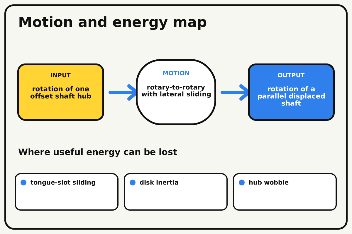
- Input
- rotation of one offset shaft hub
- Output
- rotation of a parallel displaced shaft
- Motion
- rotary-to-rotary with lateral sliding
- Energy losses
- tongue-slot sliding, disk inertia, hub wobble, axle offset error
Why this works
Orthogonal sliding constraint
The middle disk has tongues on opposite faces at right angles. Each tongue slides in one hub slot, allowing the disk center to move while both hubs maintain nearly equal angular position.
Look for: Mark the disk center and watch it travel in a small circle twice during one shaft rotation.
Where the energy goes
Efficiency and losses
The ideal model leaves out tongue-slot sliding, disk inertia, hub wobble, axle offset error. These effects turn some input energy into heat, sound, vibration, or unwanted motion, so measured performance will be lower than an ideal calculation.
Look for: Run the build slowly and locate the first place where tongue-slot sliding becomes visible or audible.
Math bite
Set safe tongue travel
Formula: required slot travel ≈ 2 × shaft offset
- Shaft offset = 8 mm
- Center disk moves across both sides
Substitute: travel ≈ 2 × 8 mm = 16 mm
Result: Each slot needs at least about 16 mm of usable travel.
Extra end clearance prevents the tongue striking a slot end.
Real geometry depends on tongue width and hub size.
Make it behave
Test, troubleshoot, and tune
Controlled test
Start here: Run five turns with the shafts nearly aligned.
Success looks like: Input and output maintain phase while the center disk slides without hitting slot ends.
Measure: Hand force, disk-center orbit, and phase error.
Change: the parallel shaft offset
Keep constant: hub dimensions, disk, input rate, axial gap, and flags
- near zero offset
- one-module offset
- two-module offset if clear
| Symptom | Likely cause | Confirm it | Fix |
|---|---|---|---|
| A tongue hits the slot end | Offset exceeds available travel | Rotate to the largest disk displacement | Reduce offset or lengthen slots |
| The disk falls out | Retainers or tongue depth are insufficient | Pull hubs apart lightly while stopped | Add shallow outer guides and deeper engagement |
| The output wobbles | Shafts are not parallel or hubs are tilted | Measure gap around both faces | Square hubs and bearing towers |
| Effort rises sharply | Tongues bind in narrow slots | Test each sliding pair separately | Widen slots slightly and smooth contact faces |
Choose your tradeoff
Use the smallest offset the application needs. Larger offset increases sliding speed and friction; wider slots reduce binding but create angular backlash.
Keep experimenting
Try another version
Single-axis slider
Demonstrate one tongue sliding in one slot first.
Low-friction liners
Compare smooth tile and bare beam contact.
Orbit trace
Attach a marker to the disk center and trace its path.
Build together
Classroom and access options
Classroom version
Teams can compare the parallel shaft offset while keeping hub dimensions, disk, input rate, axial gap, and flags. Assign builder, tester, recorder, and explainer roles; have each team predict the result before collecting three trials.
Access adaptations
- Use high-contrast tape to distinguish input and output parts.
- Replace a small crank with a wider handle for an easier grip.
- Use oversized hubs and a bright center marker so disk orbit is easy to follow.
Reflect on the design
- How did the parallel shaft offset change the measured result?
- Where did tongue-slot sliding affect the build most strongly?
- What evidence shows that orthogonal sliding constraint explains the motion?
- Which change would improve rotation of a parallel displaced shaft without creating a new problem?
Glossary
- Orthogonal sliding constraint
- The middle disk has tongues on opposite faces at right angles.
- Input
- The action or energy supplied to a system; here it is rotation of one offset shaft hub.
- Output
- The useful response produced by a system; here it is rotation of a parallel displaced shaft.
- Efficiency
- The fraction of input energy that becomes useful output instead of friction, sound, heat, or unwanted motion.
Build your dreams
One build can start the next.
Share what you learned, change one variable, and help another builder understand what worked.
Explore more guidesSources and build notes
An original BrickLabClips interpretation of a standard mechanical mechanism.
- Mechanism verification: Standard kinematics were checked for motion direction, constraint, clearance, and likely friction points.
Written and edited by BrickLabClips. Published 2026-07-22; updated 2026-07-22.