
- Difficulty
- Advanced
- Build time
- 120-180 min
- Estimated cost
- $0-$25
- Age range
- 13-18
- Workspace
- A clear table about 90 cm wide
The finish line
What you will build
With the carrier turned, both outputs rotate; holding one output makes the other speed up, and hand-turning outputs in opposite directions can leave the carrier nearly still.
Learning goals
- Identify how rotation of the differential carrier produces two coaxial shafts with variable relative speed.
- Construct and explain a one rotary input-to-two rotary outputs system.
- Measure how which output is restrained changes performance.
- Diagnose losses caused by multiple bevel meshes and carrier friction.
Before you build
Materials, tools, and safety
Reuse-material cost: Usually under $5 with an existing kit. Supervision: Adult help recommended for sharp or heated tools.
Tools
- Ruler
- Removable tape for motion marks
Low-cost swaps
- Use equivalent brick-compatible parts from any kit.
- Use cardboard beams and straw bearings for a larger demonstration model.
- Use a large transparent cardboard bevel layout as a kinematic demonstration when compact differential parts are unavailable.
Project-specific safety
- Keep fingers, hair, and loose sleeves clear of moving parts.
- Turn the mechanism by hand; do not attach a high-speed motor.
- Turn slowly and keep hands on the outer flags, not inside the carrier where several pinch points move together.
Orient the build
Place the build so rotation of the differential carrier is on your left and two coaxial shafts with variable relative speed is on your right. Call the side facing you the front, the far side the back, the tabletop the bottom, and the opposite face the top.
Build it
Step-by-step instructions
Step 1
Build the carrier ring
Create a stiff rotating frame centered on the input axis.
Add two opposite spider-pivot locations at equal radius.
Step 2
Mount the side gears
Place matching bevel gears facing inward on independent left and right shafts.
Constrain shafts axially without coupling them.
Step 3
Install first spider
Mesh one small bevel gear with both side gears on a carrier pin.
Check equal contact on both faces.
Builder checkpoint: After install first spider, the first subassembly should stay aligned when handled gently.
Step 4
Add the opposite spider
Install a second spider 180 degrees away to balance forces.
Verify both spiders share the same plane.
Watch for: If this stage binds or drifts, inspect gear backlash before adding more parts.
Step 5
Close and brace carrier
Connect carrier sides without touching rotating side shafts.
Spin the carrier empty and inspect wobble.
Step 6
Add the carrier drive
Attach a hand ring or large gear to rotate the carrier slowly.
Mark carrier and output shafts with unique flags.
Builder checkpoint: After add the carrier drive, operate the build slowly and confirm that two coaxial shafts with variable relative speed begins without binding.
Step 7
Test both outputs free
Turn the carrier five times and count both output turns.
Correct any side that binds or lags heavily.
Step 8
Run relative-motion tests
Hold one output, then counter-rotate both outputs by hand.
Record carrier and free-output behavior in each case.
Builder checkpoint: At the final checkpoint, With the carrier turned, both outputs rotate; holding one output makes the other speed up, and hand-turning outputs in opposite directions can leave the carrier nearly still.
See the engineering
Why it works
- Input
- rotation of the differential carrier
- Output
- two coaxial shafts with variable relative speed
- Motion
- one rotary input-to-two rotary outputs
- Energy losses
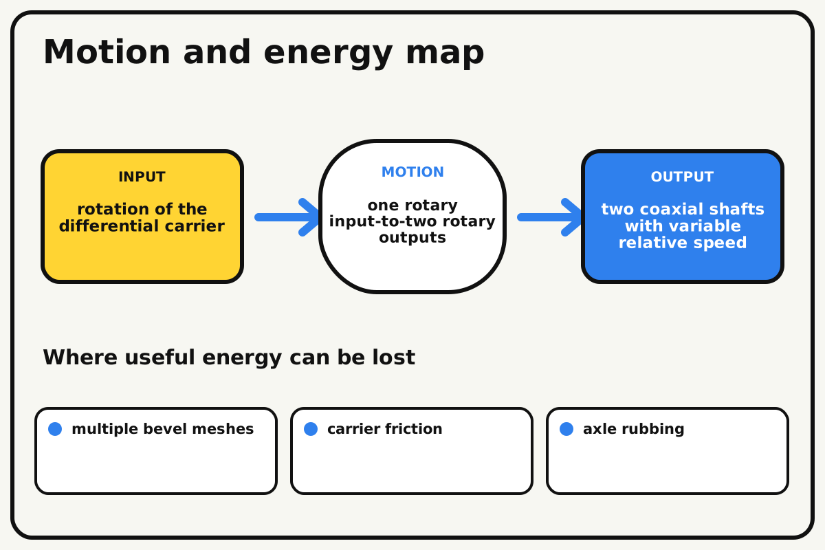
- multiple bevel meshes, carrier friction, axle rubbing, gear backlash
Why this works
Differential speed relationship
Spider gears roll between two side gears. Their carrier speed equals the average of the two output speeds, allowing one output to slow as the other speeds up while maintaining the relationship.
Look for: Hold one output flag and count how the free output changes compared with the both-free case.
Where the energy goes
Efficiency and losses
The ideal model leaves out multiple bevel meshes, carrier friction, axle rubbing, gear backlash. These effects turn some input energy into heat, sound, vibration, or unwanted motion, so measured performance will be lower than an ideal calculation.
Look for: Run the build slowly and locate the first place where multiple bevel meshes becomes visible or audible.
Math bite
Use the average-speed rule
Formula: carrier speed = (left speed + right speed) / 2
- Left output = 0 rpm
- Carrier = 10 rpm
Substitute: 10 = (0 + right)/2, so right = 20 rpm
Result: If one output stops ideally, the other turns twice carrier speed.
The equation describes kinematics, not equal traction at both outputs.
Gear friction and hand resistance cause measured deviations.
Make it behave
Test, troubleshoot, and tune
Controlled test
Start here: Turn the carrier five slow rotations with both outputs free.
Success looks like: Both output flags rotate smoothly and no spider gear climbs out of mesh.
Measure: Carrier, left, and right rotations for each condition.
Change: which output is restrained
Keep constant: carrier input turns, gear set, frame, markers, and hand speed
- both outputs free
- left held
- equal opposite output turns
| Symptom | Likely cause | Confirm it | Fix |
|---|---|---|---|
| One output never turns | Its side gear or shaft is binding | Remove spiders and spin outputs separately | Realign bearings and restore side clearance |
| Spider gears climb out | Carrier flex or axial spacing is excessive | Hold one output and watch the pivots | Brace carrier and add collars |
| Outputs turn unevenly when free | Friction differs between sides | Swap flags and hand-test each shaft | Match bearing spacing and lubrication-free clearance |
| Carrier wobbles | Spider mass or frame geometry is unbalanced | Rotate slowly and view from the side | Match opposite parts and square supports |
Choose your tradeoff
Symmetry is the first tuning tool. Match side bearings, spider positions, and gear depth before judging the speed relationship; tight meshes may look controlled but can prevent differential action.
Keep experimenting
Try another version
Open-frame differential
Run one spider gear and hand-held side gears at very low load.
Wheel-turn model
Attach equal wheels and roll the chassis through a curve.
Limited-slip comparison
Add gentle output friction and discuss how it changes behavior without calling it a true lock.
Build together
Classroom and access options
Classroom version
Teams can compare which output is restrained while keeping carrier input turns, gear set, frame, markers, and hand speed. Assign builder, tester, recorder, and explainer roles; have each team predict the result before collecting three trials.
Access adaptations
- Use high-contrast tape to distinguish input and output parts.
- Replace a small crank with a wider handle for an easier grip.
- Use different tactile shapes on left, right, and carrier flags so their rotations can be counted separately.
Reflect on the design
- How did which output is restrained change the measured result?
- Where did multiple bevel meshes affect the build most strongly?
- What evidence shows that differential speed relationship explains the motion?
- Which change would improve two coaxial shafts with variable relative speed without creating a new problem?
Glossary
- Differential speed relationship
- Spider gears roll between two side gears.
- Input
- The action or energy supplied to a system; here it is rotation of the differential carrier.
- Output
- The useful response produced by a system; here it is two coaxial shafts with variable relative speed.
- Efficiency
- The fraction of input energy that becomes useful output instead of friction, sound, heat, or unwanted motion.
Build your dreams
One build can start the next.
Share what you learned, change one variable, and help another builder understand what worked.
Explore more guidesSources and build notes
An original BrickLabClips interpretation of a standard mechanical mechanism.
- Mechanism verification: Standard kinematics were checked for motion direction, constraint, clearance, and likely friction points.
Written and edited by BrickLabClips. Published 2026-07-22; updated 2026-07-22.