
- Difficulty
- Intermediate
- Build time
- 60-95 min
- Estimated cost
- $0-$8
- Age range
- 10-18
- Workspace
- A clear table about 90 cm wide
The finish line
What you will build
One start action triggers five distinct stages and closes a battery-powered continuity switch on four of five runs.
Learning goals
- Identify how one deliberate release at stage one produces momentary low-voltage switch closure.
- Construct and explain a sequential falling, rolling, and lever motions-to-linear press system.
- Measure how target size at the weakest interface changes performance.
- Diagnose losses caused by handoff misalignment and surface friction.
Before you build
Materials, tools, and safety
Reuse-material cost: $0-$3 with reused materials. Supervision: Adult help recommended for sharp or heated tools.
Tools
- Ruler
- Pencil
- Scissors
- Timer or phone stopwatch
Low-cost swaps
- Use reclaimed paper and packaging while keeping material limits equal for every team.
- Replace metal test weights with labeled bags of coins or washers.
- Use a paper flag as the final output when no low-voltage tester is available.
Project-specific safety
- Keep load and drop tests below shoulder height and away from faces.
- Clear the test zone before releasing moving objects or suspended loads.
- Use only contained lightweight objects and a battery-powered tester; no mains electricity, projectiles, glass, or elevated drops.
Orient the build
Place the build so one deliberate release at stage one is on your left and momentary low-voltage switch closure is on your right. Call the side facing you the front, the far side the back, the tabletop the bottom, and the opposite face the top.
Build it
Step-by-step instructions
Step 1
Define the switch press
Measure the cap travel and force using a finger or spring scale.
Build the last lever to exceed both safely.
Step 2
Build backward one stage
Use a falling cup or rolling ball to move the final lever.
Test this pair five times.
Step 3
Add the middle lever
Make a broad target that receives the previous output.
Add stops so it cannot jump past the next trigger.
Builder checkpoint: After add the middle lever, the first subassembly should stay aligned when handled gently.
Step 4
Create a contained ramp
Guide a large ball between walls into the middle target.
Use a release gate rather than hand push.
Watch for: If this stage binds or drifts, inspect reset variation before adding more parts.
Step 5
Add the first stage
Place dominoes or card standups that open the gate.
Mark spacing with a jig.
Step 6
Separate early triggers
Tap the table lightly and confirm later stages remain ready.
Widen bases where vibration causes early movement.
Builder checkpoint: After separate early triggers, operate the build slowly and confirm that momentary low-voltage switch closure begins without binding.
Step 7
Run interface trials
Test each adjacent pair five times and record misses.
Tune the lowest-performing connection.
Step 8
Run five full sequences
Reset from a numbered photo checklist.
Count switch closures and first failures.
Builder checkpoint: At the final checkpoint, One start action triggers five distinct stages and closes a battery-powered continuity switch on four of five runs.
See the engineering
Why it works
- Input
- one deliberate release at stage one
- Output
- momentary low-voltage switch closure
- Motion
- sequential falling, rolling, and lever motions-to-linear press
- Energy losses
- handoff misalignment, surface friction, trigger flex, reset variation
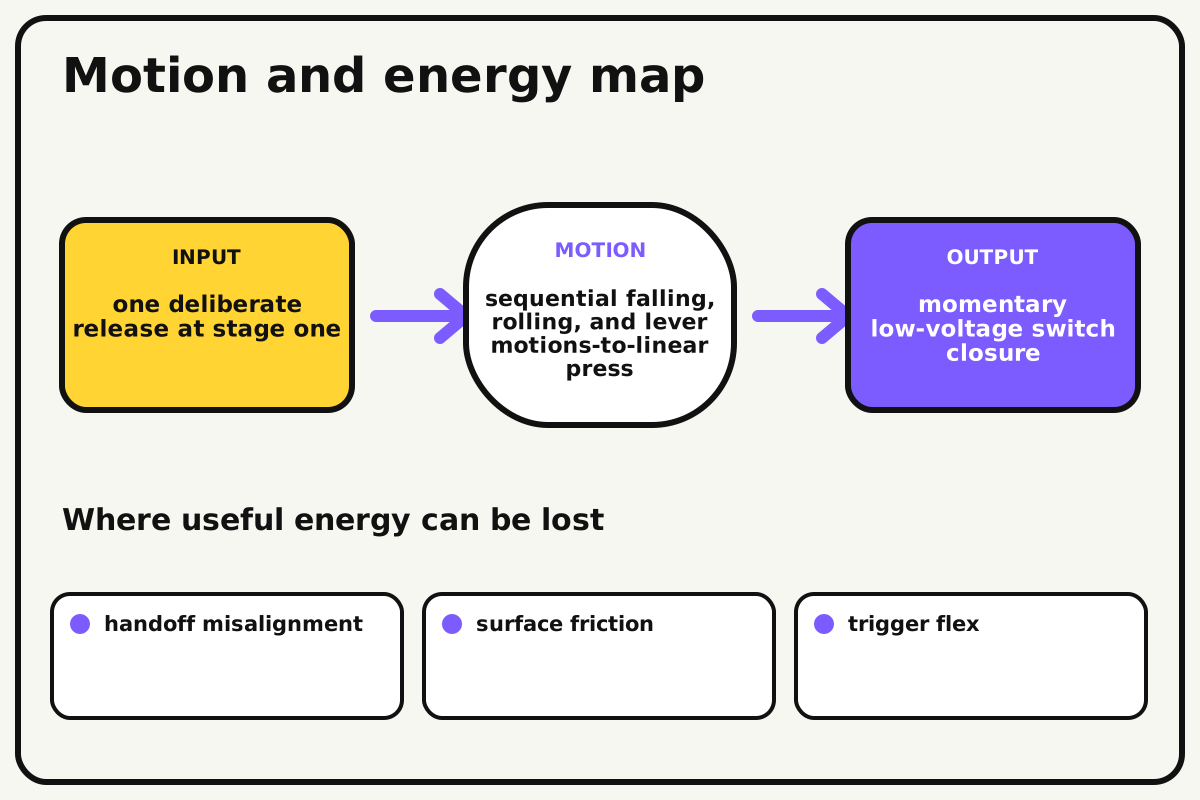
Why this works
System interfaces
Each stage is a subsystem with an input and output. The whole machine works only when every output has enough travel, force, and accuracy to trigger the next input.
Look for: Label the five interfaces and record the first failed handoff instead of only marking the full run as failed.
Where the energy goes
Efficiency and losses
The ideal model leaves out handoff misalignment, surface friction, trigger flex, reset variation. These effects turn some input energy into heat, sound, vibration, or unwanted motion, so measured performance will be lower than an ideal calculation.
Look for: Run the build slowly and locate the first place where handoff misalignment becomes visible or audible.
Math bite
Estimate full-system reliability
Formula: system probability = p1 × p2 × p3 × p4 × p5
- Each stage reliability p = 0.95
- Five stages
Substitute: probability = 0.95⁵ = 0.774
Result: Five 95-percent stages produce about 77 percent ideal full-run reliability.
Improving every handoff matters.
Stage failures may not be independent in a real machine.
Make it behave
Test, troubleshoot, and tune
Controlled test
Start here: Test the final switch lever by hand before connecting earlier stages.
Success looks like: Four of five complete runs close the switch from one start action.
Measure: First failed stage, switch closure, run time, and reset errors.
Change: target size at the weakest interface
Keep constant: five stages, objects, positions, start energy, table, and switch
- baseline target
- 2 cm wider
- 4 cm wider
| Symptom | Likely cause | Confirm it | Fix |
|---|---|---|---|
| The switch is not pressed fully | Final lever travel or force is low | Trigger the last stage alone | Move the pivot or increase safe falling mass slightly |
| A stage fires early | Vibration reaches an unstable trigger | Tap near stage one | Widen bases and increase spacing |
| The ball misses | Ramp exit and target do not align | Run only that interface | Add side guides and enlarge target |
| Reset creates new failures | Positions are not documented | Compare with ready-state photo | Add numbered outlines and checklist |
Choose your tradeoff
Improve the least reliable interface before adding spectacle. Larger targets and clean stops improve reliability, while sensitive triggers reduce needed energy but increase early firing.
Keep experimenting
Try another version
Three-stage switch
Use dominoes, ramp, and lever.
Nine-of-ten goal
Reach 90 percent full-run reliability.
Dual output
Press the switch and raise a paper message.
Build together
Classroom and access options
Classroom version
Teams can compare target size at the weakest interface while keeping five stages, objects, positions, start energy, table, and switch. Assign builder, tester, recorder, and explainer roles; have each team predict the result before collecting three trials.
Access adaptations
- Assign varied roles such as designer, builder, tester, recorder, and presenter.
- Provide pre-measured materials and a visual checklist when helpful.
- Assign one team member per stage, use large start controls, and mark all reset positions in high contrast.
Reflect on the design
- How did target size at the weakest interface change the measured result?
- Where did handoff misalignment affect the build most strongly?
- What evidence shows that system interfaces explains the motion?
- Which change would improve momentary low-voltage switch closure without creating a new problem?
Glossary
- System interfaces
- Each stage is a subsystem with an input and output.
- Input
- The action or energy supplied to a system; here it is one deliberate release at stage one.
- Output
- The useful response produced by a system; here it is momentary low-voltage switch closure.
- Efficiency
- The fraction of input energy that becomes useful output instead of friction, sound, heat, or unwanted motion.
Build your dreams
One build can start the next.
Share what you learned, change one variable, and help another builder understand what worked.
Explore more guidesSources and build notes
A common classroom engineering challenge implemented with original constraints, diagrams, and measurement guidance.
- Classroom challenge basis: A controlled-variable engineering activity with original constraints, scoring ideas, and measurement guidance.
Written and edited by BrickLabClips. Published 2026-07-22; updated 2026-07-22.
Next builds
Related guides
Chain Reaction Machine
Link ramps, levers, rolling objects, and falling cups into a reliable multi-stage machine that completes one simple task.
Cardboard Arcade Button
Build a large springy push button that closes a foil contact and can trigger a low-voltage game input or continuity test.
Brick-compatible mechanismsMechanical Counter
Advance a numbered wheel one step per input event and carry from ones to tens after a full revolution.