
- Difficulty
- Intermediate
- Build time
- 90-140 min
- Estimated cost
- $0-$24
- Age range
- 12-17
- Workspace
- A clear table about 90 cm wide
The finish line
What you will build
The claw grips and releases five different 10-30 gram foam or paper objects without stalling or crushing them.
Learning goals
- Identify how button or potentiometer command produces symmetric jaw opening and closing.
- Construct and explain a servo rotation-to-opposed jaw rotation system.
- Measure how closed servo angle changes performance.
- Diagnose losses caused by linkage backlash and jaw flex.
Before you build
Materials, tools, and safety
Reuse-material cost: Usually under $5 with an existing kit. Supervision: Adult guidance recommended for wiring and cutting.
Tools
- Small screwdriver
- Wire stripper
- Multimeter
- Low-temperature glue gun or tape
Low-cost swaps
- Use alligator-clip leads for a no-solder version.
- Build and test the mechanism manually before adding electronics.
- Operate the same claw with a hand lever and string before adding the servo.
Wiring table
| From | To | Purpose |
|---|---|---|
| Regulated 5 V | Servo red wire | Supply rated servo current |
| Supply GND | Servo ground and controller GND | Create common reference |
| Controller pin 9 | Servo signal | Command jaw position |
| Buttons | Pins 2, 3 and GND | Request open or closed state with pull-ups |
Project-specific safety
- Use only the listed low-voltage battery supply; never use mains electricity.
- Disconnect power before changing wires and stop if a motor, wire, or battery becomes warm.
- Use soft lightweight targets, keep fingers out of jaws, set angle limits before attachment, and disconnect power for adjustments.
Orient the build
Place the build so button or potentiometer command is on your left and symmetric jaw opening and closing is on your right. Call the side facing you the front, the far side the back, the tabletop the bottom, and the opposite face the top.
Build it
Step-by-step instructions
Step 1
Build the claw frame
Laminate a base with two equal pivot positions.
Mark center grip line.
Step 2
Make matched jaws
Cut two mirror-image jaws and add broad padded tips.
Drill or punch pivots with adult help.
Step 3
Install pivots
Attach jaws with free-running gaps and hard open stops.
Confirm equal manual swing.
Builder checkpoint: After install pivots, the first subassembly should stay aligned when handled gently.
Step 4
Connect the jaws
Use a tie link so one driven jaw mirrors the other.
Adjust hole positions for symmetric closure.
Watch for: If this stage binds or drifts, inspect pad compression before adding more parts.
Step 5
Mount the servo
Fix its body rigidly and align the horn near the drive-jaw link.
Keep load sideways forces off the shaft.
Step 6
Wire safe power
Use regulated 5 V and common ground, then connect signal and buttons.
Test servo unattached at 40 and 120 degrees.
Builder checkpoint: After wire safe power, operate the build slowly and confirm that symmetric jaw opening and closing begins without binding.
Step 7
Calibrate limits
Attach the linkage at midpoint and approach open and closed stops slowly.
Record safe angles before gripping.
Step 8
Run object trials
Grip, lift 5 cm, hold five seconds, and release each soft object.
Stop on buzzing or stalled motion.
Builder checkpoint: At the final checkpoint, The claw grips and releases five different 10-30 gram foam or paper objects without stalling or crushing them.
See the engineering
Why it works
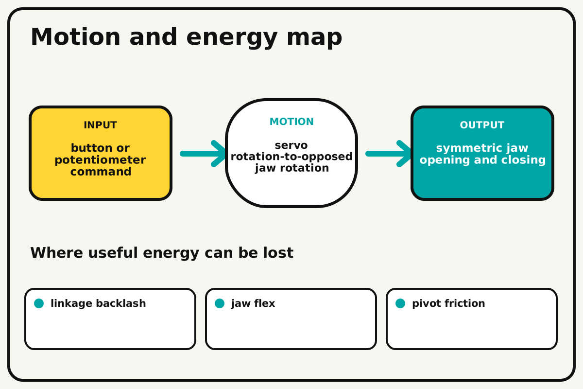
- Input
- button or potentiometer command
- Output
- symmetric jaw opening and closing
- Motion
- servo rotation-to-opposed jaw rotation
- Energy losses
- linkage backlash, jaw flex, pivot friction, pad compression
Why this works
Servo-linkage actuation
The servo horn moves a link that rotates one jaw; a tie link or meshed sector makes the second jaw mirror it. Hard stops protect both mechanism and servo.
Look for: Measure jaw gap at five servo angles and note where the relationship becomes nonlinear.
Where the energy goes
Efficiency and losses
The ideal model leaves out linkage backlash, jaw flex, pivot friction, pad compression. These effects turn some input energy into heat, sound, vibration, or unwanted motion, so measured performance will be lower than an ideal calculation.
Look for: Run the build slowly and locate the first place where linkage backlash becomes visible or audible.
Math bite
Estimate jaw-tip travel
Formula: arc length = radius × angle in radians
- Jaw radius = 0.08 m
- Angle = 35° = 0.611 rad
Substitute: travel = 0.08 × 0.611 = 0.049 m
Result: Each jaw tip follows about a 4.9 cm arc.
The opening width changes by geometry of both jaws.
Links and pads alter the actual path.servo_claw.ino
A complete two-button claw controller that moves gradually between calibrated safe angles.
#include <Servo.h>
Servo claw; const int openButton=2, closeButton=3;
int position=45; const int openAngle=45, closedAngle=112;
void setup(){ pinMode(openButton,INPUT_PULLUP); pinMode(closeButton,INPUT_PULLUP); claw.attach(9); claw.write(position); }
void loop(){
  int target=position;
  if(!digitalRead(openButton)) target=openAngle;
  if(!digitalRead(closeButton)) target=closedAngle;
  if(position<target) position++;
  if(position>target) position--;
  claw.write(position); delay(18);
}
Make it behave
Test, troubleshoot, and tune
Controlled test
Start here: Cycle the claw empty through safe angles five times.
Success looks like: It grips and releases five lightweight objects without stall or damage.
Measure: Object success, jaw angle, gap, servo sound, and supply current.
Change: closed servo angle
Keep constant: claw, power, pads, object set, lift height, and hold time
- wide stop
- medium stop
- narrow safe stop
| Symptom | Likely cause | Confirm it | Fix |
|---|---|---|---|
| Servo buzzes closed | Command pushes beyond a hard stop | Disconnect power and move jaws manually | Reduce close angle |
| One jaw moves more | Tie-link holes or pivots differ | Measure gaps from center | Match geometry and loosen pivots |
| Objects slip | Pads or jaw path provide little contact | Close gently without lifting | Enlarge compliant pads |
| Controller resets | Servo current sags supply | Watch logic LED while closing | Use rated servo supply with common ground |
Choose your tradeoff
Use the widest closing angle that holds the object without stalling. More grip force can crush targets and shorten servo life; compliant pads often help more than extra torque.
Keep experimenting
Try another version
Hand-lever claw
Tune linkage before wiring.
Object variety
Grip round, flat, and irregular soft targets.
Force limit
Use a current or force sensor to stop closing automatically.
Build together
Classroom and access options
Classroom version
Teams can compare closed servo angle while keeping claw, power, pads, object set, lift height, and hold time. Assign builder, tester, recorder, and explainer roles; have each team predict the result before collecting three trials.
Access adaptations
- Color-code and label every wire at both ends.
- Use clip leads, larger controls, and pre-crimped connectors when fine motor work is difficult.
- Use two large open/close buttons and a wide object-loading tray.
Reflect on the design
- How did closed servo angle change the measured result?
- Where did linkage backlash affect the build most strongly?
- What evidence shows that servo-linkage actuation explains the motion?
- Which change would improve symmetric jaw opening and closing without creating a new problem?
Glossary
- Servo-linkage actuation
- The servo horn moves a link that rotates one jaw; a tie link or meshed sector makes the second jaw mirror it.
- Input
- The action or energy supplied to a system; here it is button or potentiometer command.
- Output
- The useful response produced by a system; here it is symmetric jaw opening and closing.
- Efficiency
- The fraction of input energy that becomes useful output instead of friction, sound, heat, or unwanted motion.
Build your dreams
One build can start the next.
Share what you learned, change one variable, and help another builder understand what worked.
Explore more guidesSources and build notes
A platform-agnostic low-voltage robotics or electronics project with original assembly guidance.
- Low-voltage design review: Battery voltage, polarity, component roles, current paths, and motor or LED protection were editorially checked.
Written and edited by BrickLabClips. Published 2026-07-22; updated 2026-07-22.