
- Difficulty
- Beginner
- Build time
- 45-70 min
- Estimated cost
- $0-$12
- Age range
- 10-16
- Workspace
- A clear table about 90 cm wide
The finish line
What you will build
The model cycles through valid light states, accepts one pedestrian request, and never illuminates red and green together.
Learning goals
- Identify how elapsed time and pedestrian button event produces safe red-yellow-green LED sequence.
- Construct and explain a digital events-to-visible state changes system.
- Measure how button press timing changes performance.
- Diagnose losses caused by button bounce and timing drift.
Before you build
Materials, tools, and safety
Reuse-material cost: Usually under $5 with an existing kit. Supervision: Adult guidance recommended for wiring and cutting.
Tools
- Small screwdriver
- Wire stripper
- Multimeter
- Low-temperature glue gun or tape
Low-cost swaps
- Use alligator-clip leads for a no-solder version.
- Build and test the mechanism manually before adding electronics.
- Use a block-coding microcontroller board with built-in LEDs and button.
Wiring table
| From | To | Purpose |
|---|---|---|
| Pins 8, 9, 10 | Red, yellow, green LED anodes through 220 Ω each | Control lights with limited current |
| LED cathodes | GND | Complete each LED circuit |
| Button | Pin 2 and GND | Create active-low request input |
| USB 5 V | Controller | Supply low-voltage logic power |
Project-specific safety
- Use only the listed low-voltage battery supply; never use mains electricity.
- Disconnect power before changing wires and stop if a motor, wire, or battery becomes warm.
- Use USB or battery low voltage only, include one resistor per external LED, and disconnect before changing wiring.
Orient the build
Place the build so elapsed time and pedestrian button event is on your left and safe red-yellow-green LED sequence is on your right. Call the side facing you the front, the far side the back, the tabletop the bottom, and the opposite face the top.
Build it
Step-by-step instructions
Step 1
Plan valid states
Draw red, red-yellow transition if desired, green, yellow, and pedestrian red states.
Choose safe durations.
Step 2
Build the light housing
Place LEDs vertically with labels and opaque dividers.
Keep leads from touching.
Step 3
Add current resistors
Connect each anode to its own 220-330 Ω resistor and digital pin.
Connect cathodes to ground.
Builder checkpoint: After add current resistors, the first subassembly should stay aligned when handled gently.
Step 4
Wire the button
Connect it between pin 2 and ground using the internal pull-up.
Label pressed as LOW.
Watch for: If this stage binds or drifts, inspect blocking delays before adding more parts.
Step 5
Test one LED at a time
Upload a short output test and verify color-to-pin mapping.
Correct wiring with power disconnected.
Step 6
Program the states
Use millis timing and one function that sets all three LEDs.
Prevent conflicting outputs.
Builder checkpoint: After program the states, operate the build slowly and confirm that safe red-yellow-green LED sequence begins without binding.
Step 7
Add the request flag
Record button presses and serve the request at the next safe transition.
Clear the flag afterward.
Step 8
Audit ten cycles
Log every state and press the button at different moments.
Confirm no unsafe color combination.
Builder checkpoint: At the final checkpoint, The model cycles through valid light states, accepts one pedestrian request, and never illuminates red and green together.
See the engineering
Why it works
- Input
- elapsed time and pedestrian button event
- Output
- safe red-yellow-green LED sequence
- Motion
- digital events-to-visible state changes
- Energy losses
- button bounce, timing drift, wiring errors, blocking delays
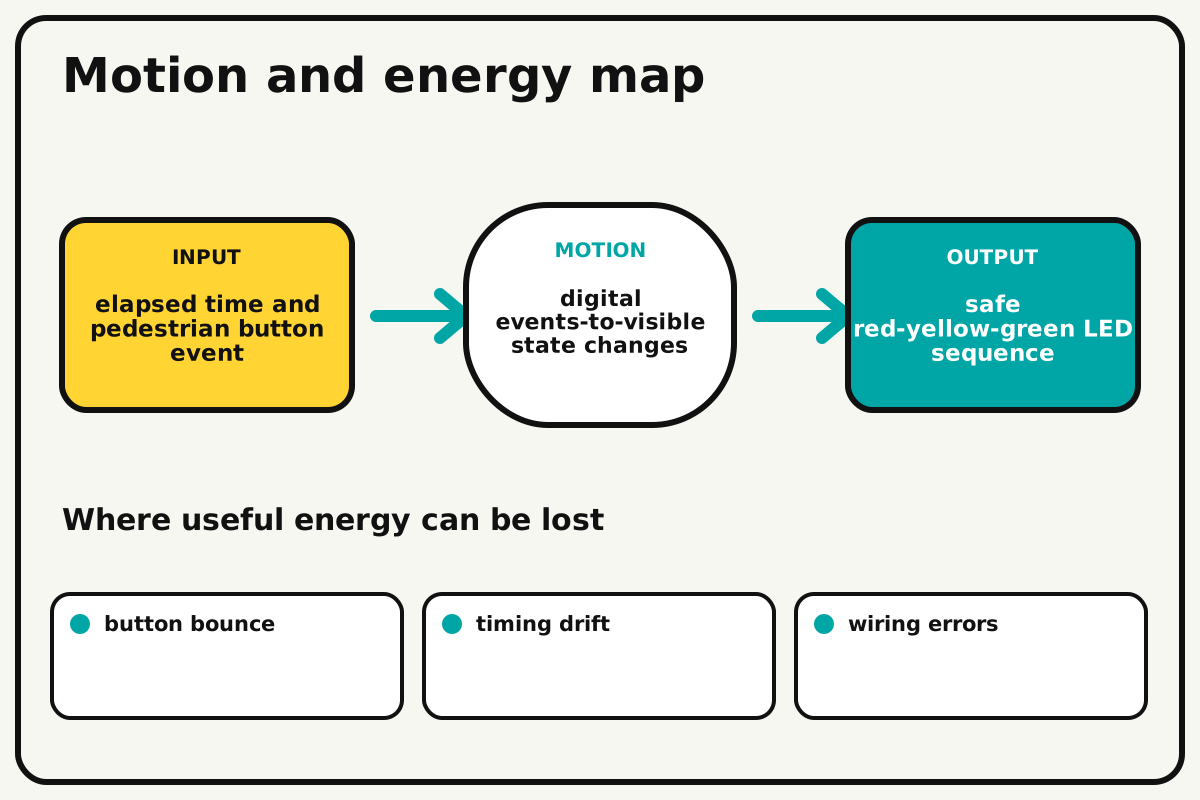
Why this works
Finite-state control
The program stores one current state and transitions only along allowed paths. A button sets a request flag that is handled at a safe point in the cycle.
Look for: Write the current state beside each LED pattern and confirm there is no direct green-to-red transition without yellow.
Where the energy goes
Efficiency and losses
The ideal model leaves out button bounce, timing drift, wiring errors, blocking delays. These effects turn some input energy into heat, sound, vibration, or unwanted motion, so measured performance will be lower than an ideal calculation.
Look for: Run the build slowly and locate the first place where button bounce becomes visible or audible.
Math bite
Find cycle duration
Formula: cycle time = green + yellow + red
- Green = 8 s
- Yellow = 2 s
- Red = 6 s
Substitute: cycle = 8 + 2 + 6 = 16 s
Result: The normal cycle repeats every 16 seconds.
A pedestrian request may extend red time.
Button timing and loop execution add milliseconds.traffic_light.ino
A complete nonblocking state machine with an edge-captured request flag.
enum State { GREEN, YELLOW, RED };
const int redLed=8, yellowLed=9, greenLed=10, buttonPin=2;
State state=GREEN; unsigned long stateStarted=0; bool request=false, lastButton=false;
void setLights(bool r,bool y,bool g){ digitalWrite(redLed,r); digitalWrite(yellowLed,y); digitalWrite(greenLed,g); }
void enter(State next){ state=next; stateStarted=millis(); if(state==GREEN)setLights(0,0,1); if(state==YELLOW)setLights(0,1,0); if(state==RED)setLights(1,0,0); }
void setup(){ pinMode(redLed,OUTPUT); pinMode(yellowLed,OUTPUT); pinMode(greenLed,OUTPUT); pinMode(buttonPin,INPUT_PULLUP); enter(GREEN); }
void loop(){
  bool pressed=!digitalRead(buttonPin); if(pressed && !lastButton) request=true; lastButton=pressed;
  unsigned long elapsed=millis()-stateStarted;
  if(state==GREEN && (elapsed>=8000 || (request && elapsed>=3000))) enter(YELLOW);
  else if(state==YELLOW && elapsed>=2000) enter(RED);
  else if(state==RED && elapsed>=(request?8000UL:6000UL)){ request=false; enter(GREEN); }
}
Make it behave
Test, troubleshoot, and tune
Controlled test
Start here: Test each LED output separately before running the sequence.
Success looks like: Ten cycles show only valid states and one request is handled without red-green overlap.
Measure: State order, duration, request latency, and invalid combinations.
Change: button press timing
Keep constant: code, LEDs, resistors, durations, power, and observer
- press during green
- press during yellow
- press during red
| Symptom | Likely cause | Confirm it | Fix |
|---|---|---|---|
| Wrong LED lights | Pin mapping or polarity is wrong | Run the one-at-a-time test | Reconnect with power off or fix constants |
| Button triggers repeatedly | Input floats or bounces | Log raw state while held | Use pull-up and edge detection |
| Sequence freezes | Blocking delay prevents transitions | Inspect timing code | Use millis-based state timing |
| Red and green overlap | Outputs are changed in separate paths | Log every state change | Use one setLights function that sets all outputs |
Choose your tradeoff
Keep transition logic explicit before shortening timings. Faster cycles are convenient for testing, but state order and button behavior must stay identical.
Keep experimenting
Try another version
Fixed cycle
Remove the button and use three timed states.
Nonblocking countdown
Display seconds while still reading the button.
Two-direction intersection
Add a second light with conflict-free paired states.
Build together
Classroom and access options
Classroom version
Teams can compare button press timing while keeping code, leds, resistors, durations, power, and observer. Assign builder, tester, recorder, and explainer roles; have each team predict the result before collecting three trials.
Access adaptations
- Color-code and label every wire at both ends.
- Use clip leads, larger controls, and pre-crimped connectors when fine motor work is difficult.
- Arrange LEDs vertically with raised R, Y, and G labels and add a large pedestrian button.
Reflect on the design
- How did button press timing change the measured result?
- Where did button bounce affect the build most strongly?
- What evidence shows that finite-state control explains the motion?
- Which change would improve safe red-yellow-green LED sequence without creating a new problem?
Glossary
- Finite-state control
- The program stores one current state and transitions only along allowed paths.
- Input
- The action or energy supplied to a system; here it is elapsed time and pedestrian button event.
- Output
- The useful response produced by a system; here it is safe red-yellow-green LED sequence.
- Efficiency
- The fraction of input energy that becomes useful output instead of friction, sound, heat, or unwanted motion.
Build your dreams
One build can start the next.
Share what you learned, change one variable, and help another builder understand what worked.
Explore more guidesSources and build notes
A platform-agnostic low-voltage robotics or electronics project with original assembly guidance.
- Low-voltage design review: Battery voltage, polarity, component roles, current paths, and motor or LED protection were editorially checked.
Written and edited by BrickLabClips. Published 2026-07-22; updated 2026-07-22.