
- Difficulty
- Intermediate
- Build time
- 60-90 min
- Estimated cost
- $0-$18
- Age range
- 12-17
- Workspace
- A clear table about 90 cm wide
The finish line
What you will build
The meter reports targets from 10 to 100 cm with average error under 3 cm across five marked positions.
Learning goals
- Identify how ultrasonic trigger pulse and returning echo produces calculated distance in centimetres.
- Construct and explain a sound pulse travel-to-digital measurement system.
- Measure how target angle changes performance.
- Diagnose losses caused by angled reflections and soft targets.
Before you build
Materials, tools, and safety
Reuse-material cost: Usually under $5 with an existing kit. Supervision: Adult guidance recommended for wiring and cutting.
Tools
- Small screwdriver
- Wire stripper
- Multimeter
- Low-temperature glue gun or tape
Low-cost swaps
- Use alligator-clip leads for a no-solder version.
- Build and test the mechanism manually before adding electronics.
- Use a classroom distance-sensor board with built-in level shifting when the controller uses 3.3 V logic.
Wiring table
| From | To | Purpose |
|---|---|---|
| Sensor VCC and GND | Rated 5 V and common ground | Power ultrasonic module |
| Controller pin 9 | Sensor trigger | Send 10-microsecond pulse |
| Sensor echo | Controller pin 10 | Measure return pulse; level-shift for 3.3 V logic |
| USB | Controller and serial monitor | Power logic and show distance |
Project-specific safety
- Use only the listed low-voltage battery supply; never use mains electricity.
- Disconnect power before changing wires and stop if a motor, wire, or battery becomes warm.
- Use only rated low voltage, do not place the sensor at ears, and add a voltage divider on echo when a 3.3 V controller requires it.
Orient the build
Place the build so ultrasonic trigger pulse and returning echo is on your left and calculated distance in centimetres is on your right. Call the side facing you the front, the far side the back, the tabletop the bottom, and the opposite face the top.
Build it
Step-by-step instructions
Step 1
Mount the sensor
Fix the two transducers level on a card stand.
Keep the front openings clear.
Step 2
Wire rated power
Connect VCC and ground, then join trigger and echo to chosen pins.
Add level shifting if the board requires it.
Step 3
Send a clean trigger
Drive trigger low, high for 10 microseconds, then low.
Wait between measurements.
Builder checkpoint: After send a clean trigger, the first subassembly should stay aligned when handled gently.
Step 4
Read echo duration
Use a timeout so missing echoes cannot freeze the program.
Print raw microseconds.
Watch for: If this stage binds or drifts, inspect timing resolution before adding more parts.
Step 5
Convert to distance
Multiply duration by 0.0343 cm/µs and divide by two.
Reject zero or out-of-range values.
Step 6
Build a calibration lane
Mark 10, 25, 50, 75, and 100 cm from the sensor face.
Align the flat target square.
Builder checkpoint: After build a calibration lane, operate the build slowly and confirm that calculated distance in centimetres begins without binding.
Step 7
Collect five readings
Average at each mark and record range.
Pause between samples.
Step 8
Test target angle
Rotate the target 15 and 30 degrees at 50 cm.
Explain unstable reflections.
Builder checkpoint: At the final checkpoint, The meter reports targets from 10 to 100 cm with average error under 3 cm across five marked positions.
See the engineering
Why it works
- Input
- ultrasonic trigger pulse and returning echo
- Output
- calculated distance in centimetres
- Motion
- sound pulse travel-to-digital measurement
- Energy losses
- angled reflections, soft targets, air temperature, timing resolution
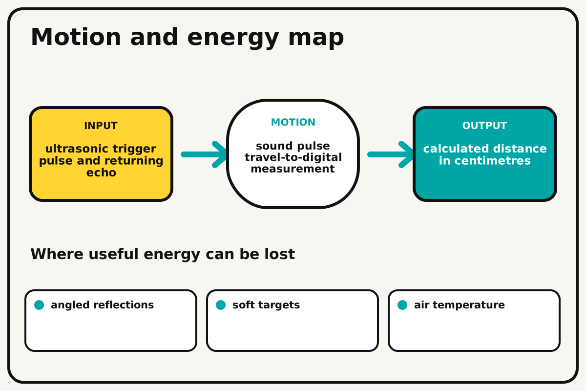
Why this works
Echo time of flight
A sound burst travels to the target and back. Multiplying round-trip time by sound speed and dividing by two gives one-way distance.
Look for: Rotate a flat card target and note how readings become unstable when the echo reflects away from the receiver.
Where the energy goes
Efficiency and losses
The ideal model leaves out angled reflections, soft targets, air temperature, timing resolution. These effects turn some input energy into heat, sound, vibration, or unwanted motion, so measured performance will be lower than an ideal calculation.
Look for: Run the build slowly and locate the first place where angled reflections becomes visible or audible.
Math bite
Convert echo time to distance
Formula: distance = echo time × sound speed / 2
- Echo time = 2915 µs
- Sound speed = 0.0343 cm/µs
Substitute: distance = 2915 × 0.0343 / 2 = 50.0 cm
Result: The target is about 50 centimetres away.
Division by two accounts for the outgoing and returning path.
Temperature and target angle affect the result.distance_meter.ino
A complete serial distance meter with timeout and invalid-reading handling.
const int triggerPin=9, echoPin=10;
void setup(){ pinMode(triggerPin,OUTPUT); pinMode(echoPin,INPUT); Serial.begin(9600); }
void loop(){
  digitalWrite(triggerPin,LOW); delayMicroseconds(3);
  digitalWrite(triggerPin,HIGH); delayMicroseconds(10); digitalWrite(triggerPin,LOW);
  unsigned long duration=pulseIn(echoPin,HIGH,30000UL);
  if(duration==0){ Serial.println("No echo"); }
  else { float distanceCm=duration*0.0343f/2.0f; Serial.print(distanceCm,1); Serial.println(" cm"); }
  delay(100);
}
Make it behave
Test, troubleshoot, and tune
Controlled test
Start here: Read a flat target at 25 cm before testing the full range.
Success looks like: Average error is below 3 cm from 10 to 100 cm at five positions.
Measure: Measured distance, known distance, error, and reading range.
Change: target angle
Keep constant: sensor, code, power, room, target material, and sample count
- 0° square target
- 15° target
- 30° target
| Symptom | Likely cause | Confirm it | Fix |
|---|---|---|---|
| Readings are zero | Echo is missing or pins are swapped | Print raw pulse duration | Correct pin mapping and target position |
| Distance doubles | Round-trip path was not divided by two | Check the formula | Divide by two once |
| Values jump | Target is angled, soft, or too small | Use a large square card | Align and enlarge target |
| Program freezes | Pulse measurement has no timeout | Remove target and observe | Add a finite timeout and invalid reading state |
Choose your tradeoff
Align the target before adding software smoothing. Averaging reduces random variation but can hide fast distance changes.
Keep experimenting
Try another version
Three-point meter
Measure 20, 50, and 80 cm.
Median filter
Compare median and average across noisy readings.
Parking display
Map distance to LEDs without fabricating precision.
Build together
Classroom and access options
Classroom version
Teams can compare target angle while keeping sensor, code, power, room, target material, and sample count. Assign builder, tester, recorder, and explainer roles; have each team predict the result before collecting three trials.
Access adaptations
- Color-code and label every wire at both ends.
- Use clip leads, larger controls, and pre-crimped connectors when fine motor work is difficult.
- Display large text and add tones whose spacing changes with distance, keeping volume comfortable.
Reflect on the design
- How did target angle change the measured result?
- Where did angled reflections affect the build most strongly?
- What evidence shows that echo time of flight explains the motion?
- Which change would improve calculated distance in centimetres without creating a new problem?
Glossary
- Echo time of flight
- A sound burst travels to the target and back.
- Input
- The action or energy supplied to a system; here it is ultrasonic trigger pulse and returning echo.
- Output
- The useful response produced by a system; here it is calculated distance in centimetres.
- Efficiency
- The fraction of input energy that becomes useful output instead of friction, sound, heat, or unwanted motion.
Build your dreams
One build can start the next.
Share what you learned, change one variable, and help another builder understand what worked.
Explore more guidesSources and build notes
A platform-agnostic low-voltage robotics or electronics project with original assembly guidance.
- Low-voltage design review: Battery voltage, polarity, component roles, current paths, and motor or LED protection were editorially checked.
Written and edited by BrickLabClips. Published 2026-07-22; updated 2026-07-22.