
- Difficulty
- Advanced
- Build time
- 150-240 min
- Estimated cost
- $0-$18
- Age range
- 13-18
- Workspace
- A clear table about 90 cm wide
The finish line
What you will build
Two joints move through controlled ranges without major leaks, hold a lightweight pose briefly, and lift a 20-gram paper cup over a protected tray.
Learning goals
- Identify how hand force on control syringes produces angular motion at shoulder and elbow joints.
- Construct and explain a linear fluid input-to-angular arm motion system.
- Measure how the output-syringe pivot distance from the joint changes performance.
- Diagnose losses caused by air compression and seal friction.
Before you build
Materials, tools, and safety
Reuse-material cost: Usually under $5 with an existing kit. Supervision: Adult help recommended for sharp or heated tools.
Tools
- Ruler
- Pencil
- Scissors
- Low-temperature glue gun or tape
- Adult-operated craft knife
- Pliers for snug tubing
Low-cost swaps
- Use clean shipping-box cardboard instead of buying sheets.
- Replace hot glue with strong tape and folded tabs.
- Build the same arm with string tendons for a dry version when tubing or syringes are unavailable.
Project-specific safety
- An adult should handle craft knives and make difficult starter cuts.
- Let hot glue cool before pressing a joint or testing moving parts.
- Use only needle-free syringes, test over a waterproof tray, and keep all water away from electronics.
Orient the build
Place the build so hand force on control syringes is on your left and angular motion at shoulder and elbow joints is on your right. Call the side facing you the front, the far side the back, the tabletop the bottom, and the opposite face the top.
Build it
Step-by-step instructions
Step 1
Laminate the base and tower
Glue multiple corrugated layers with alternating flute directions.
Brace the vertical shoulder pivot on both sides.
Step 2
Build upper and forearm beams
Laminate two box-section beams and mark pivot centers at least 2 cm from edges.
Add reinforcement patches around every hole.
Step 3
Assemble the arm joints
Join shoulder and elbow with loose but supported pivots.
Move the arm manually through safe ranges.
Builder checkpoint: After assemble the arm joints, the first subassembly should stay aligned when handled gently.
Step 4
Mount output syringes
Pin each syringe body to one link and plunger end to another at measured lever arms.
Check full stroke without bottoming out.
Watch for: If this stage binds or drifts, inspect joint leakage before adding more parts.
Step 5
Prepare hydraulic pairs
Fill syringe, tube, and partner syringe completely with water.
Tap out every visible air bubble before connecting.
Step 6
Mount the controls
Secure input syringes to the base so hands do not pull tubing.
Leave gentle tubing loops at moving joints.
Builder checkpoint: After mount the controls, operate the build slowly and confirm that angular motion at shoulder and elbow joints begins without binding.
Step 7
Test one joint at a time
Move slowly over the tray and mark safe plunger limits.
Fix leaks and flex before connecting both circuits.
Step 8
Lift a paper cup
Place a 20-gram cup near the arm, move both controls gradually, and lift 5 cm.
Stop if cardboard softens or a syringe reaches its stop.
Builder checkpoint: At the final checkpoint, Two joints move through controlled ranges without major leaks, hold a lightweight pose briefly, and lift a 20-gram paper cup over a protected tray.
See the engineering
Why it works
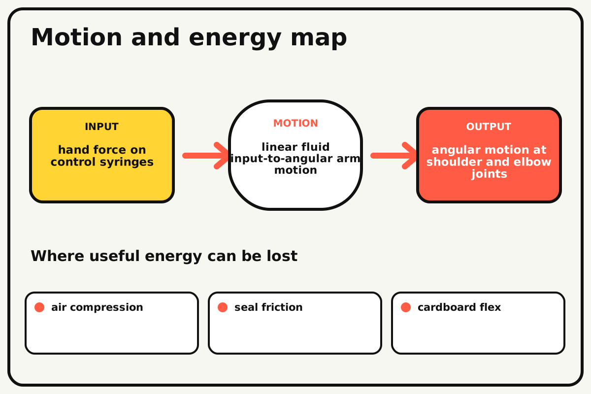
- Input
- hand force on control syringes
- Output
- angular motion at shoulder and elbow joints
- Motion
- linear fluid input-to-angular arm motion
- Energy losses
- air compression, seal friction, cardboard flex, joint leakage
Why this works
Pascal pressure transmission
Pressure applied to a confined liquid is transmitted through the tubing. Output force depends on piston area, while the actuator's lever arm converts cylinder force into joint torque.
Look for: Compare a water-filled line with an air-bubbled line and feel the difference in response.
Where the energy goes
Efficiency and losses
The ideal model leaves out air compression, seal friction, cardboard flex, joint leakage. These effects turn some input energy into heat, sound, vibration, or unwanted motion, so measured performance will be lower than an ideal calculation.
Look for: Run the build slowly and locate the first place where air compression becomes visible or audible.
Math bite
Compare hydraulic force
Formula: output force = input force × output area / input area
- Input area = 1.0 cm²
- Output area = 2.0 cm²
- Input force = 5 N
Substitute: output force = 5 × 2/1 = 10 N
Result: The ideal larger output piston produces twice the force.
Its travel is correspondingly smaller for equal fluid volume.
Seal friction, air, tubing stretch, and arm leverage reduce real output.
Make it behave
Test, troubleshoot, and tune
Controlled test
Start here: Move each unloaded joint through half its range over the waterproof tray.
Success looks like: Motion begins promptly, tubing stays connected, and the arm lifts 20 grams without major leaks.
Measure: Input travel, output angle, leaked drops, and held mass.
Change: the output-syringe pivot distance from the joint
Keep constant: syringes, water volume, arm, load, tubing, and input stroke
- near pivot
- middle lever arm
- farther lever arm
| Symptom | Likely cause | Confirm it | Fix |
|---|---|---|---|
| The arm feels springy | Air remains in the hydraulic line | Hold tube vertically and inspect bubbles | Refill and purge air |
| A joint barely moves | Syringe geometry is near a dead center | Move arm by hand and inspect angle | Relocate actuator pivot |
| The frame bends | Cardboard section or pivot patch is weak | Apply half stroke and watch tower | Laminate and triangulate |
| Water leaks at tubing | Connection is loose or tube cracked | Dry the joint and press slowly | Trim tube end and reconnect snugly |
Choose your tradeoff
Actuator position trades range for torque. A connection farther from the joint increases leverage but may need more syringe travel; remove air before interpreting any geometry change.
Keep experimenting
Try another version
One-joint arm
Build only the shoulder circuit first.
Cylinder-size comparison
Pair different syringe diameters and measure force-travel tradeoff.
Three-axis arm
Add a low-load base rotation using a separate dry linkage.
Build together
Classroom and access options
Classroom version
Teams can compare the output-syringe pivot distance from the joint while keeping syringes, water volume, arm, load, tubing, and input stroke. Assign builder, tester, recorder, and explainer roles; have each team predict the result before collecting three trials.
Access adaptations
- Pre-cut repeated pieces and mark fold lines with high-contrast ink.
- Use large tabs, binder clips, and tape for easier one-handed assembly.
- Mount input syringes horizontally in large holders and label each joint with color and tactile marks.
Reflect on the design
- How did the output-syringe pivot distance from the joint change the measured result?
- Where did air compression affect the build most strongly?
- What evidence shows that pascal pressure transmission explains the motion?
- Which change would improve angular motion at shoulder and elbow joints without creating a new problem?
Glossary
- Pascal pressure transmission
- Pressure applied to a confined liquid is transmitted through the tubing.
- Input
- The action or energy supplied to a system; here it is hand force on control syringes.
- Output
- The useful response produced by a system; here it is angular motion at shoulder and elbow joints.
- Efficiency
- The fraction of input energy that becomes useful output instead of friction, sound, heat, or unwanted motion.
Build your dreams
One build can start the next.
Share what you learned, change one variable, and help another builder understand what worked.
Explore more guidesSources and build notes
An original BrickLabClips cardboard machine with dimensionally specified construction.
- Cardboard design verification: Dimensions, fold allowances, repeated-motion joints, and likely load paths received an editorial geometry review.
Written and edited by BrickLabClips. Published 2026-07-22; updated 2026-07-22.