
- Difficulty
- Intermediate
- Build time
- 60-90 min
- Estimated cost
- $0-$12
- Age range
- 11-17
- Workspace
- A clear table about 90 cm wide
The finish line
What you will build
The lift raises a 100-gram platform at least 5 cm, holds it for ten seconds, and completes five cycles without visible leakage.
Learning goals
- Identify how hand force and travel at the control syringe produces upward force and travel at the lift syringe.
- Construct and explain a linear fluid displacement-to-linear lift motion system.
- Measure how input and output syringe size changes performance.
- Diagnose losses caused by trapped air and seal friction.
Before you build
Materials, tools, and safety
Reuse-material cost: Usually under $5 with an existing kit. Supervision: Adult help recommended for sharp or heated tools.
Tools
- Ruler
- Pencil
- Scissors
- Masking tape
- Towels
- Binder clips
Low-cost swaps
- Use clean recycled packaging whenever it has similar stiffness.
- Substitute paper clips, binder clips, or twist ties for specialty fasteners.
- Use two equal needle-free syringes for a one-to-one displacement demonstration.
Project-specific safety
- Wear eye protection when stretched elastic, magnets, or spinning parts are present.
- Test at floor or tabletop height and keep the path clear of people.
- Use only needle-free syringes and clean water, work over a tray, keep water away from electronics, and never aim a disconnected tube at a face.
Orient the build
Place the build so hand force and travel at the control syringe is on your left and upward force and travel at the lift syringe is on your right. Call the side facing you the front, the far side the back, the tabletop the bottom, and the opposite face the top.
Build it
Step-by-step instructions
Step 1
Build the guide frame
Mount two straight vertical rails on a wide base inside the spill tray.
Brace them so they stay parallel.
Step 2
Make the lift platform
Attach sleeves that slide along both rails without tilting.
Place the output syringe beneath the center.
Step 3
Fill the circuit
Draw colored water into both syringes and tubing until no large bubble remains.
Tap and purge air with tips upward.
Builder checkpoint: After fill the circuit, the first subassembly should stay aligned when handled gently.
Step 4
Connect securely
Push tubing fully onto both syringe tips and add cable ties or tape strain relief.
Keep plungers near mid-travel.
Watch for: If this stage binds or drifts, inspect platform rubbing before adding more parts.
Step 5
Mount the output
Fix the larger syringe body vertically while its plunger supports the platform.
Align force through the platform center.
Step 6
Check an empty cycle
Press the input slowly and guide the platform through one full stroke.
Stop if tubing swells or leaks.
Builder checkpoint: After check an empty cycle, operate the build slowly and confirm that upward force and travel at the lift syringe begins without binding.
Step 7
Add the test load
Center 100 grams in a bag and raise it 5 cm at low speed.
Hold the input still for ten seconds.
Step 8
Compare syringe roles
Record input and output travel, then swap syringe sizes after draining safely.
Refill, purge, and repeat.
Builder checkpoint: At the final checkpoint, The lift raises a 100-gram platform at least 5 cm, holds it for ten seconds, and completes five cycles without visible leakage.
See the engineering
Why it works
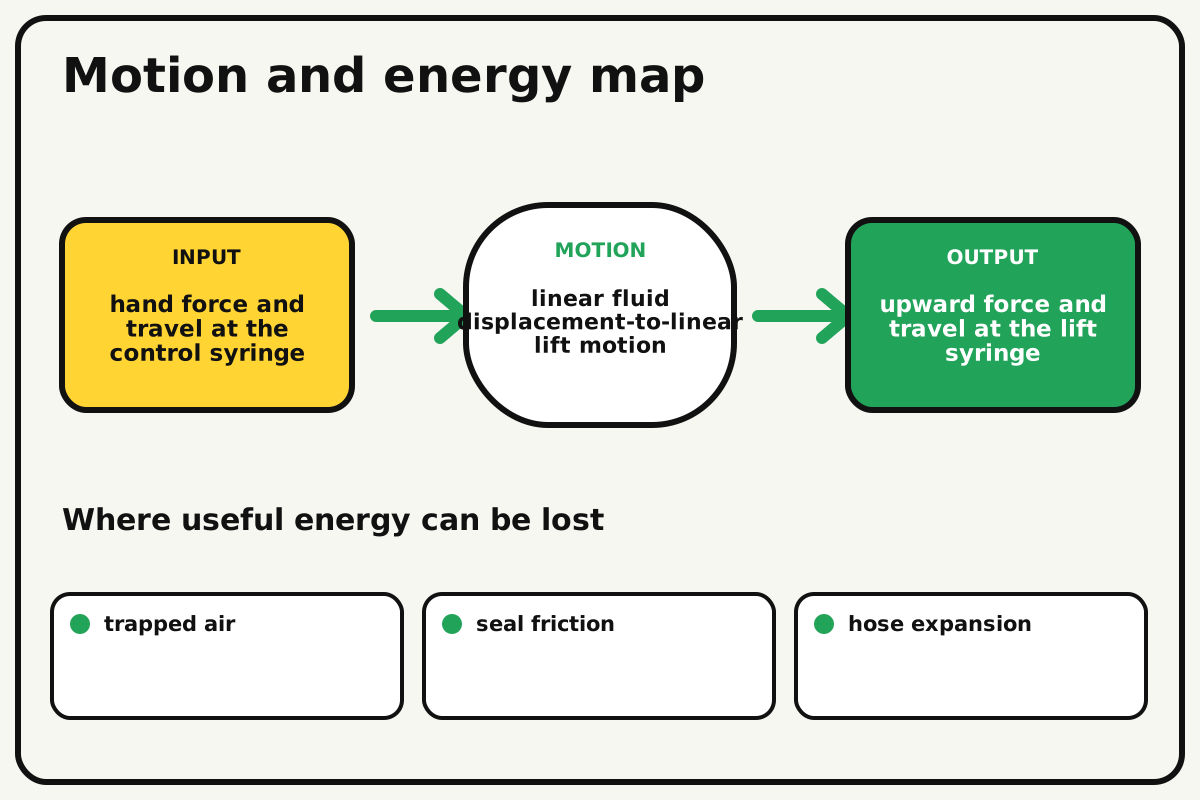
- Input
- hand force and travel at the control syringe
- Output
- upward force and travel at the lift syringe
- Motion
- linear fluid displacement-to-linear lift motion
- Energy losses
- trapped air, seal friction, hose expansion, platform rubbing
Why this works
Hydraulic pressure transmission
Pressure applied to a confined liquid acts throughout the system. A larger output piston can create greater force but moves a shorter distance for the same displaced fluid volume.
Look for: Press slowly and watch whether the output starts immediately; delayed motion often reveals trapped air or frame flex.
Where the energy goes
Efficiency and losses
The ideal model leaves out trapped air, seal friction, hose expansion, platform rubbing. These effects turn some input energy into heat, sound, vibration, or unwanted motion, so measured performance will be lower than an ideal calculation.
Look for: Run the build slowly and locate the first place where trapped air becomes visible or audible.
Math bite
Estimate ideal force ratio
Formula: force ratio = output piston area / input piston area
- Input area = 1.0 cm²
- Output area = 2.0 cm²
Substitute: force ratio = 2.0 / 1.0 = 2
Result: The ideal output force is twice the input force.
Output travel is approximately half the input travel for equal displaced volume.
Seal friction, hose expansion, and air reduce real performance.
Make it behave
Test, troubleshoot, and tune
Controlled test
Start here: Cycle the empty platform once over the spill tray.
Success looks like: The system raises 100 grams by 5 cm, holds ten seconds, and shows no visible leak in five cycles.
Measure: Input travel, output travel, supported mass, and pressure drift.
Change: input and output syringe size
Keep constant: water fill, tubing, frame, load, speed, and starting plunger positions
- equal syringes
- small input and large output
- large input and small output
| Symptom | Likely cause | Confirm it | Fix |
|---|---|---|---|
| The lift feels springy | Air remains in the circuit | Hold tubing upright and compress gently | Purge bubbles and reconnect |
| The platform tilts | Output is off-center or guides bind | Lift empty and watch both sleeves | Recenter the syringe and realign rails |
| It sinks while held | A seal or connection leaks | Mark plunger position and inspect droplets | Tighten joints or replace the syringe |
| The input will not move | A plunger is at its stop or tubing is pinched | Disconnect over the tray and inspect | Reset mid-stroke and open the hose path |
Choose your tradeoff
Remove air and align the platform before increasing load. A larger output piston raises more force ideally, but it gives up travel and may need more input stroke.
Keep experimenting
Try another version
Equal-syringe demo
Lift an empty platform and compare travel.
Load curve
Add mass in 25-gram steps and record maximum height.
Pressure estimate
Calculate load force divided by output piston area and compare configurations.
Build together
Classroom and access options
Classroom version
Teams can compare input and output syringe size while keeping water fill, tubing, frame, load, speed, and starting plunger positions. Assign builder, tester, recorder, and explainer roles; have each team predict the result before collecting three trials.
Access adaptations
- Offer pre-cut parts and tactile or high-contrast measurement marks.
- Split roles so one builder can hold, another assemble, and another measure.
- Add a wide plunger pad, large measurement marks, and a partner role for holding the frame while another operates the syringe.
Reflect on the design
- How did input and output syringe size change the measured result?
- Where did trapped air affect the build most strongly?
- What evidence shows that hydraulic pressure transmission explains the motion?
- Which change would improve upward force and travel at the lift syringe without creating a new problem?
Glossary
- Hydraulic pressure transmission
- Pressure applied to a confined liquid acts throughout the system.
- Input
- The action or energy supplied to a system; here it is hand force and travel at the control syringe.
- Output
- The useful response produced by a system; here it is upward force and travel at the lift syringe.
- Efficiency
- The fraction of input energy that becomes useful output instead of friction, sound, heat, or unwanted motion.
Build your dreams
One build can start the next.
Share what you learned, change one variable, and help another builder understand what worked.
Explore more guidesSources and build notes
A familiar household engineering activity implemented with original instructions and controlled tests.
- Classroom engineering basis: A common educational challenge implemented with original dimensions, tests, diagrams, and instructions.
Written and edited by BrickLabClips. Published 2026-07-22; updated 2026-07-22.
Next builds
Related guides
Water-Hydraulic Cardboard Robot Arm
Move a reinforced cardboard arm with paired water-filled syringes that transmit force and displacement through tubing.
Classroom challengesMechanical Advantage Lift Challenge
Choose a lever, pulley, wheel-and-axle, or combination system to lift the same load with the smallest measured input force.
Pulley Elevator
Raise a small platform with fixed and movable pulleys, then compare input force, rope travel, and mechanical advantage.