
- Difficulty
- Beginner
- Build time
- 45-70 min
- Estimated cost
- $0-$8
- Age range
- 10-16
- Workspace
- A clear table about 90 cm wide
The finish line
What you will build
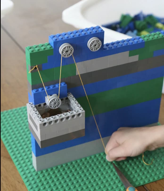
The guided platform raises 30 cm with a 200-gram load, remains level, and completes five lifts without the line leaving a pulley.
Learning goals
- Identify how downward pull on a free rope end produces upward platform travel.
- Construct and explain a linear pull-to-opposite linear lift system.
- Measure how number of supporting rope segments changes performance.
- Diagnose losses caused by axle friction and rope rubbing.
Before you build
Materials, tools, and safety
Reuse-material cost: $0-$3 with reused materials. Supervision: Adult help recommended for sharp or heated tools.
Tools
- Ruler
- Pencil
- Scissors
- Timer or phone stopwatch
Low-cost swaps
- Use reclaimed paper and packaging while keeping material limits equal for every team.
- Replace metal test weights with labeled bags of coins or washers.
- Use thread spools on pencils as pulleys and a labeled bag of coins as the load.
Project-specific safety
- Keep load and drop tests below shoulder height and away from faces.
- Clear the test zone before releasing moving objects or suspended loads.
- Keep the load below 250 grams, test below shoulder height, secure every support, and keep fingers clear of moving line and pulley grooves.
Orient the build
Place the build so downward pull on a free rope end is on your left and upward platform travel is on your right. Call the side facing you the front, the far side the back, the tabletop the bottom, and the opposite face the top.
Build it
Step-by-step instructions
Step 1
Brace the tower
Build a wide base and two parallel vertical guides.
Push lightly in each direction and reinforce movement.
Step 2
Make the platform
Add two loose sleeves that slide on the guides and a centered load cup.
Confirm it cannot rotate off the rails.
Step 3
Mount the fixed pulley
Support its axle on both sides at the tower top.
Align the groove directly above the platform center.
Builder checkpoint: After mount the fixed pulley, the first subassembly should stay aligned when handled gently.
Step 4
Test direction change
Tie the line to the platform, route over the pulley, and pull down.
Lift the empty platform 10 cm slowly.
Watch for: If this stage binds or drifts, inspect frame flex before adding more parts.
Step 5
Add the movable pulley
Attach a second pulley beneath the platform and anchor one line end at the top.
Route down, around, and back up to the pull side.
Step 6
Mark travel distances
Place tape marks every 10 cm on the input line and tower.
Reset platform and scale to zero.
Builder checkpoint: After mark travel distances, operate the build slowly and confirm that upward platform travel begins without binding.
Step 7
Lift the test load
Add 200 grams and raise it 30 cm with each setup.
Record peak force and rope travel.
Step 8
Compare configurations
Repeat three trials for fixed-only and movable-pulley systems.
Keep load, speed, height, and scale angle fixed.
Builder checkpoint: At the final checkpoint, The guided platform raises 30 cm with a 200-gram load, remains level, and completes five lifts without the line leaving a pulley.
See the engineering
Why it works
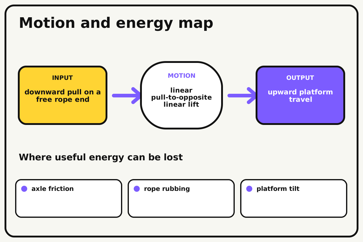
- Input
- downward pull on a free rope end
- Output
- upward platform travel
- Motion
- linear pull-to-opposite linear lift
- Energy losses
- axle friction, rope rubbing, platform tilt, frame flex
Why this works
Pulley mechanical advantage
A movable pulley shares the load across supporting rope segments. Ideal input force falls as the number of supporting segments increases, while required rope travel increases by the same factor.
Look for: Mark the rope every 10 cm and compare hand travel with platform travel in each pulley arrangement.
Where the energy goes
Efficiency and losses
The ideal model leaves out axle friction, rope rubbing, platform tilt, frame flex. These effects turn some input energy into heat, sound, vibration, or unwanted motion, so measured performance will be lower than an ideal calculation.
Look for: Run the build slowly and locate the first place where axle friction becomes visible or audible.
Math bite
Calculate ideal input force
Formula: input force = load force / supporting rope segments
- Load force = 2.0 N
- Supporting segments = 2
Substitute: input force = 2.0 / 2 = 1.0 N
Result: The ideal two-segment system needs about 1 newton of input force.
The hand must pull about twice the platform travel.
Pulley and rope friction make measured force higher.
Make it behave
Test, troubleshoot, and tune
Controlled test
Start here: Raise the empty platform 10 cm before adding mass.
Success looks like: The system raises 200 grams by 30 cm for five cycles without derailment.
Measure: Peak input force, rope travel, platform travel, and tilt.
Change: number of supporting rope segments
Keep constant: load, platform, tower, lift height, pull speed, and spring scale
- fixed pulley only
- one movable pulley
- same movable setup after alignment tuning
| Symptom | Likely cause | Confirm it | Fix |
|---|---|---|---|
| The rope leaves the groove | Pulley and load are misaligned | View the system from front and side | Recenter the axle and add guide flanges |
| The platform tilts | Lift point is off-center or guides bind | Raise empty and compare sleeve motion | Center the line and loosen sleeves |
| Measured force is high | Axles rub or rope bends sharply | Spin pulleys unloaded | Widen bearing gaps and smooth the route |
| The tower leans | Base or top brace is weak | Pull lightly with no load | Add diagonal bracing and a wider base |
Choose your tradeoff
Reduce rubbing before increasing load. More supporting line segments reduce ideal force, but every extra bend adds friction and requires more pull distance.
Keep experimenting
Try another version
Direction-only lift
Use one fixed pulley and an empty platform.
Efficiency test
Compare ideal and measured mechanical advantage.
Four-segment hoist
Build a second movable stage and predict rope travel.
Build together
Classroom and access options
Classroom version
Teams can compare number of supporting rope segments while keeping load, platform, tower, lift height, pull speed, and spring scale. Assign builder, tester, recorder, and explainer roles; have each team predict the result before collecting three trials.
Access adaptations
- Assign varied roles such as designer, builder, tester, recorder, and presenter.
- Provide pre-measured materials and a visual checklist when helpful.
- Add a large rope handle, high-contrast travel marks, and a partner role for reading the spring scale.
Reflect on the design
- How did number of supporting rope segments change the measured result?
- Where did axle friction affect the build most strongly?
- What evidence shows that pulley mechanical advantage explains the motion?
- Which change would improve upward platform travel without creating a new problem?
Glossary
- Pulley mechanical advantage
- A movable pulley shares the load across supporting rope segments.
- Input
- The action or energy supplied to a system; here it is downward pull on a free rope end.
- Output
- The useful response produced by a system; here it is upward platform travel.
- Efficiency
- The fraction of input energy that becomes useful output instead of friction, sound, heat, or unwanted motion.
Build your dreams
One build can start the next.
Share what you learned, change one variable, and help another builder understand what worked.
Explore more guidesSources and build notes
A common classroom engineering challenge implemented with original constraints, diagrams, and measurement guidance.
- Classroom challenge basis: A controlled-variable engineering activity with original constraints, scoring ideas, and measurement guidance.
Written and edited by BrickLabClips. Published 2026-07-22; updated 2026-07-22.