
- Difficulty
- Beginner
- Build time
- 45-70 min
- Estimated cost
- $0-$5
- Age range
- 10-16
- Workspace
- A clear table about 90 cm wide
The finish line
What you will build
In a shaded viewing area, the screen shows a recognizable inverted bright scene with sharper detail at the smaller tested aperture.
Learning goals
- Identify how light rays through a pinhole produces inverted image on a translucent screen.
- Construct and explain a light propagation through a small aperture system.
- Measure how the aperture diameter changes performance.
- Diagnose losses caused by limited light and box leaks.
Before you build
Materials, tools, and safety
Reuse-material cost: $0-$3 with reused materials. Supervision: Adult help recommended for sharp or heated tools.
Tools
- Ruler
- Pencil
- Scissors
- Low-temperature glue gun or tape
- Push pin used by an adult
- Adult-operated craft knife
Low-cost swaps
- Use clean shipping-box cardboard instead of buying sheets.
- Replace hot glue with strong tape and folded tabs.
- Use wax paper or thin white tissue as the screen and a clean snack box as the chamber.
Project-specific safety
- An adult should handle craft knives and make difficult starter cuts.
- Let hot glue cool before pressing a joint or testing moving parts.
- Never point the camera obscura at the sun; use bright buildings or landscapes instead.
Orient the build
Place the build so light rays through a pinhole is on your left and inverted image on a translucent screen is on your right. Call the side facing you the front, the far side the back, the tabletop the bottom, and the opposite face the top.
Build it
Step-by-step instructions
Step 1
Darken the box interior
Line all inside faces with matte black paper and cover seam gaps.
Leave the lid removable for screen access.
Step 2
Cut the aperture window
Make a 4 cm square opening centered in one short wall.
Leave a strong border around it.
Step 3
Prepare pinhole foils
Tape foil over three cardboard frames and pierce small, medium, and larger clean holes.
Label the frames without touching the holes.
Builder checkpoint: After prepare pinhole foils, the first subassembly should stay aligned when handled gently.
Step 4
Build the screen
Cut a large window in the opposite wall and tape tracing paper flat over it.
Prevent wrinkles and light gaps.
Watch for: If this stage binds or drifts, inspect oversized aperture before adding more parts.
Step 5
Seal the chamber
Close every seam except the pinhole and screen with dark tape.
Enter a dim room and check for light leaks.
Step 6
Aim at a bright scene
Place the screen end under a dark viewing hood and point the aperture outward.
Wait for eyes to adjust.
Builder checkpoint: After aim at a bright scene, operate the build slowly and confirm that inverted image on a translucent screen begins without binding.
Step 7
Focus by distance
Slide an optional inner screen closer to or farther from the pinhole.
Compare image size and brightness.
Step 8
Compare apertures
Use the same scene for all three holes and rate sharpness and brightness.
Avoid sunlight during every trial.
Builder checkpoint: At the final checkpoint, In a shaded viewing area, the screen shows a recognizable inverted bright scene with sharper detail at the smaller tested aperture.
See the engineering
Why it works
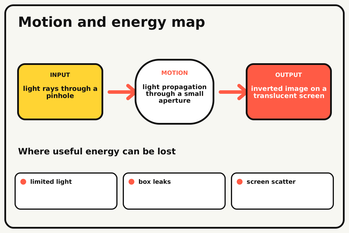
- Input
- light rays through a pinhole
- Output
- inverted image on a translucent screen
- Motion
- light propagation through a small aperture
- Energy losses
- limited light, box leaks, screen scatter, oversized aperture
Why this works
Pinhole image formation
A tiny aperture admits a narrow bundle of rays from each scene point. Rays cross at the opening, so light from the top reaches the screen bottom and light from the left reaches the right.
Look for: Move a bright object upward and watch its projected image move downward.
Where the energy goes
Efficiency and losses
The ideal model leaves out limited light, box leaks, screen scatter, oversized aperture. These effects turn some input energy into heat, sound, vibration, or unwanted motion, so measured performance will be lower than an ideal calculation.
Look for: Run the build slowly and locate the first place where limited light becomes visible or audible.
Math bite
Estimate image size
Formula: image height / object height = screen distance / object distance
- Screen distance = 0.30 m
- Object distance = 3.0 m
- Object height = 1.0 m
Substitute: image height = 1.0 × 0.30/3.0 = 0.10 m
Result: The ideal image is about 10 cm tall.
Moving the screen farther enlarges and dims the image.
The relation assumes a small aperture and simple geometry.
Make it behave
Test, troubleshoot, and tune
Controlled test
Start here: Aim at a bright high-contrast building from a shaded location.
Success looks like: A recognizable inverted image appears and aperture size creates a visible sharpness-brightness tradeoff.
Measure: Image height, sharpness rating, and brightness rating.
Change: the aperture diameter
Keep constant: scene, object distance, screen distance, box, shade, and observer
- small hole
- medium hole
- larger hole
| Symptom | Likely cause | Confirm it | Fix |
|---|---|---|---|
| The screen is blank | Scene is dim or box has stray light | Cover the aperture and look for other glow | Choose a brighter scene and seal leaks |
| The image is blurry | Pinhole is large or ragged | Inspect foil against a lamp without looking at sun | Replace with a clean smaller hole |
| The image is too dim | Hole is tiny or screen distance long | Try the medium aperture | Increase hole slightly or shorten chamber |
| The image is doubled | Foil has more than one hole | Inspect and count bright points | Replace the foil patch |
Choose your tradeoff
A smaller hole improves geometric sharpness but passes less light. Adjust viewing darkness before enlarging the aperture, and keep the screen flat so one area does not appear falsely focused.
Keep experimenting
Try another version
Sun-safe lamp test
Project a bright lamp silhouette indoors without looking into it.
Sliding screen
Measure image size at three projection distances.
Trace the projection
Sketch the inverted scene lightly on the screen.
Build together
Classroom and access options
Classroom version
Teams can compare the aperture diameter while keeping scene, object distance, screen distance, box, shade, and observer. Assign builder, tester, recorder, and explainer roles; have each team predict the result before collecting three trials.
Access adaptations
- Pre-cut repeated pieces and mark fold lines with high-contrast ink.
- Use large tabs, binder clips, and tape for easier one-handed assembly.
- Use a large viewing hood and a partner who describes screen changes while another adjusts apertures.
Reflect on the design
- How did the aperture diameter change the measured result?
- Where did limited light affect the build most strongly?
- What evidence shows that pinhole image formation explains the motion?
- Which change would improve inverted image on a translucent screen without creating a new problem?
Glossary
- Pinhole image formation
- A tiny aperture admits a narrow bundle of rays from each scene point.
- Input
- The action or energy supplied to a system; here it is light rays through a pinhole.
- Output
- The useful response produced by a system; here it is inverted image on a translucent screen.
- Efficiency
- The fraction of input energy that becomes useful output instead of friction, sound, heat, or unwanted motion.
Build your dreams
One build can start the next.
Share what you learned, change one variable, and help another builder understand what worked.
Explore more guidesSources and build notes
An original BrickLabClips cardboard machine with dimensionally specified construction.
- Cardboard design verification: Dimensions, fold allowances, repeated-motion joints, and likely load paths received an editorial geometry review.
Written and edited by BrickLabClips. Published 2026-07-22; updated 2026-07-22.