
- Difficulty
- Beginner
- Build time
- 35-55 min
- Estimated cost
- $0-$6
- Age range
- 10-15
- Workspace
- A clear table about 90 cm wide
The finish line
What you will build
A viewer can see a clear object above a 30 cm visual barrier while holding the periscope vertically, with both mirrors secured behind protective windows.
Learning goals
- Identify how light entering the upper window produces redirected image at the lower viewing window.
- Construct and explain a light path redirected by two reflections system.
- Measure how the top-mirror angle changes performance.
- Diagnose losses caused by mirror absorption and misalignment.
Before you build
Materials, tools, and safety
Reuse-material cost: $0-$3 with reused materials. Supervision: Adult help recommended for sharp or heated tools.
Tools
- Ruler
- Pencil
- Scissors
- Low-temperature glue gun or tape
- Protractor
- Adult-operated craft knife
Low-cost swaps
- Use clean shipping-box cardboard instead of buying sheets.
- Replace hot glue with strong tape and folded tabs.
- Use reflective acrylic sheet rather than glass mirrors; do not use cracked or sharp glass.
Project-specific safety
- An adult should handle craft knives and make difficult starter cuts.
- Let hot glue cool before pressing a joint or testing moving parts.
- Use plastic or acrylic mirrors with covered edges and never aim the periscope at the sun or intense lights.
Orient the build
Place the build so light entering the upper window is on your left and redirected image at the lower viewing window is on your right. Call the side facing you the front, the far side the back, the tabletop the bottom, and the opposite face the top.
Build it
Step-by-step instructions
Step 1
Build the rectangular tube
Fold one scored sheet into a 10 cm square tube and overlap one seam.
Check the cross section stays square.
Step 2
Cut viewing windows
Mark one opening near the top front and one near the bottom back.
Leave at least 2 cm of wall around each.
Step 3
Make 45-degree supports
Draw right triangles with equal legs and fold two mirrored shelves.
Verify each angle with a protractor.
Builder checkpoint: After make 45-degree supports, the first subassembly should stay aligned when handled gently.
Step 4
Mount the top mirror
Face the reflective surface downward into the tube at 45 degrees.
Keep its center aligned with the top window.
Watch for: If this stage binds or drifts, inspect internal stray light before adding more parts.
Step 5
Mount the lower mirror
Face the second mirror upward at a parallel 45-degree angle.
Align it with the lower viewing window.
Step 6
Darken the interior
Line exposed inner walls with matte black paper without covering the light path.
Seal bright side gaps with tape.
Builder checkpoint: After darken the interior, operate the build slowly and confirm that redirected image at the lower viewing window begins without binding.
Step 7
Add protective windows
Tape clear plastic over both openings and cover every mirror edge.
Label the object and eye ends.
Step 8
Align the view
Look at a high-contrast target and adjust one mirror in 1-degree steps.
Secure supports after the target centers.
Builder checkpoint: At the final checkpoint, A viewer can see a clear object above a 30 cm visual barrier while holding the periscope vertically, with both mirrors secured behind protective windows.
See the engineering
Why it works
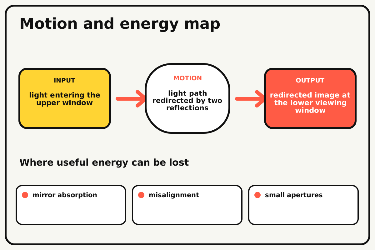
- Input
- light entering the upper window
- Output
- redirected image at the lower viewing window
- Motion
- light path redirected by two reflections
- Energy losses
- mirror absorption, misalignment, small apertures, internal stray light
Why this works
Law of reflection
Light reflects from a flat mirror so the angle of reflection equals the angle of incidence. Two parallel 45-degree mirrors redirect the path down and then outward.
Look for: Use a drawn ray line to follow light from the object to the top mirror, down the tube, and out the lower mirror.
Where the energy goes
Efficiency and losses
The ideal model leaves out mirror absorption, misalignment, small apertures, internal stray light. These effects turn some input energy into heat, sound, vibration, or unwanted motion, so measured performance will be lower than an ideal calculation.
Look for: Run the build slowly and locate the first place where mirror absorption becomes visible or audible.
Math bite
Track the reflection turn
Formula: path change at a 45° mirror = 90°
- Incoming ray is horizontal
- Mirror normal is 45° from the ray
Substitute: incidence angle = reflection angle = 45°
Result: The outgoing ray turns from horizontal to vertical.
A second parallel mirror turns it horizontal again.
Real mirror thickness and support error can shift the image.
Make it behave
Test, troubleshoot, and tune
Controlled test
Start here: View a black-and-white target 2 metres away before sealing the tube.
Success looks like: The target appears centered and visible above a 30 cm barrier without mirror movement.
Measure: Image brightness and target offset from window center.
Change: the top-mirror angle
Keep constant: tube, lower mirror, target, distance, lighting, and viewing position
- 44 degrees
- 45 degrees
- 46 degrees
| Symptom | Likely cause | Confirm it | Fix |
|---|---|---|---|
| No image appears | One mirror faces the wrong direction | Trace the ray path with a paper arrow | Rotate the incorrect mirror |
| Only part of the target appears | Windows or mirrors are too small or offset | Look straight through each opening separately | Recenter supports and widen window safely |
| The image is dim | Interior stray light or dirty mirrors reduce contrast | Test in shade and clean surfaces | Darken gaps and wipe acrylic |
| The view shifts when held | Tube twists or mirror supports flex | Gently squeeze corners while viewing | Add internal cross braces |
Choose your tradeoff
Align one mirror at a time using a fixed target. Larger mirrors and windows improve field of view but require a stiffer tube; dark inner walls improve contrast without changing geometry.
Keep experimenting
Try another version
Open ray model
Place two mirrors on a tabletop and trace the path.
Longer periscope
Extend the tube and measure added image offset.
Rotating top head
Add a safe turntable that scans left and right.
Build together
Classroom and access options
Classroom version
Teams can compare the top-mirror angle while keeping tube, lower mirror, target, distance, lighting, and viewing position. Assign builder, tester, recorder, and explainer roles; have each team predict the result before collecting three trials.
Access adaptations
- Pre-cut repeated pieces and mark fold lines with high-contrast ink.
- Use large tabs, binder clips, and tape for easier one-handed assembly.
- Make the lower viewing window wide and add tactile top/bottom orientation marks.
Reflect on the design
- How did the top-mirror angle change the measured result?
- Where did mirror absorption affect the build most strongly?
- What evidence shows that law of reflection explains the motion?
- Which change would improve redirected image at the lower viewing window without creating a new problem?
Glossary
- Law of reflection
- Light reflects from a flat mirror so the angle of reflection equals the angle of incidence.
- Input
- The action or energy supplied to a system; here it is light entering the upper window.
- Output
- The useful response produced by a system; here it is redirected image at the lower viewing window.
- Efficiency
- The fraction of input energy that becomes useful output instead of friction, sound, heat, or unwanted motion.
Build your dreams
One build can start the next.
Share what you learned, change one variable, and help another builder understand what worked.
Explore more guidesSources and build notes
An original BrickLabClips cardboard machine with dimensionally specified construction.
- Cardboard design verification: Dimensions, fold allowances, repeated-motion joints, and likely load paths received an editorial geometry review.
Written and edited by BrickLabClips. Published 2026-07-22; updated 2026-07-22.