
- Difficulty
- Intermediate
- Build time
- 90-140 min
- Estimated cost
- $0-$8
- Age range
- 11-17
- Workspace
- A clear table about 90 cm wide
The finish line
What you will build
Four laminated gears mesh without repeated binding, and the display demonstrates one reduction, one idler direction change, and one compound ratio.
Learning goals
- Identify how hand rotation of a large driver gear produces visible rotation through selectable gear paths.
- Construct and explain a rotary-to-rotary educational display system.
- Measure how the axle center distance changes performance.
- Diagnose losses caused by tooth edge rubbing and cardboard warping.
Before you build
Materials, tools, and safety
Reuse-material cost: $0-$3 with reused materials. Supervision: Adult help recommended for sharp or heated tools.
Tools
- Ruler
- Pencil
- Scissors
- Low-temperature glue gun or tape
- Compass
- Protractor
- Adult-operated craft knife
Low-cost swaps
- Use clean shipping-box cardboard instead of buying sheets.
- Replace hot glue with strong tape and folded tabs.
- Use printed gear templates that you create with a generic gear-design tool, without copying commercial instructions.
Project-specific safety
- An adult should handle craft knives and make difficult starter cuts.
- Let hot glue cool before pressing a joint or testing moving parts.
- Round every cardboard tooth corner and use a side handle so fingers stay outside meshes.
Orient the build
Place the build so hand rotation of a large driver gear is on your left and visible rotation through selectable gear paths is on your right. Call the side facing you the front, the far side the back, the tabletop the bottom, and the opposite face the top.
Build it
Step-by-step instructions
Step 1
Choose one tooth pitch
Draw all pitch circles from tooth count using one consistent module or spacing.
Label count before cutting.
Step 2
Cut and laminate gears
Glue crossed-corrugation layers, pierce exact centers, and cut teeth consistently.
Press flat while drying.
Step 3
Build the display frame
Reinforce axle zones on front and back panels with a wide open viewing area.
Keep panels parallel with spacers.
Builder checkpoint: After build the display frame, the first subassembly should stay aligned when handled gently.
Step 4
Install the first pair
Set axle centers from the sum of pitch radii and fit straw bearings.
Turn slowly and adjust half-tooth mesh.
Watch for: If this stage binds or drifts, inspect frame flex before adding more parts.
Step 5
Add an idler
Place a third matching-pitch gear between input and output.
Mark all three rotation directions.
Step 6
Add a compound shaft
Lock one small and one large gear to a shared axle in separate planes.
Align each stage with its partner.
Builder checkpoint: After add a compound shaft, operate the build slowly and confirm that visible rotation through selectable gear paths begins without binding.
Step 7
Run ratio trials
Count driver and output turns for each arrangement.
Record tooth counts and direction before changing.
Step 8
Make a display key
Label driver, idler, driven, compound shaft, ratio, and loss points.
Add removable arrows for classroom explanation.
Builder checkpoint: At the final checkpoint, Four laminated gears mesh without repeated binding, and the display demonstrates one reduction, one idler direction change, and one compound ratio.
See the engineering
Why it works
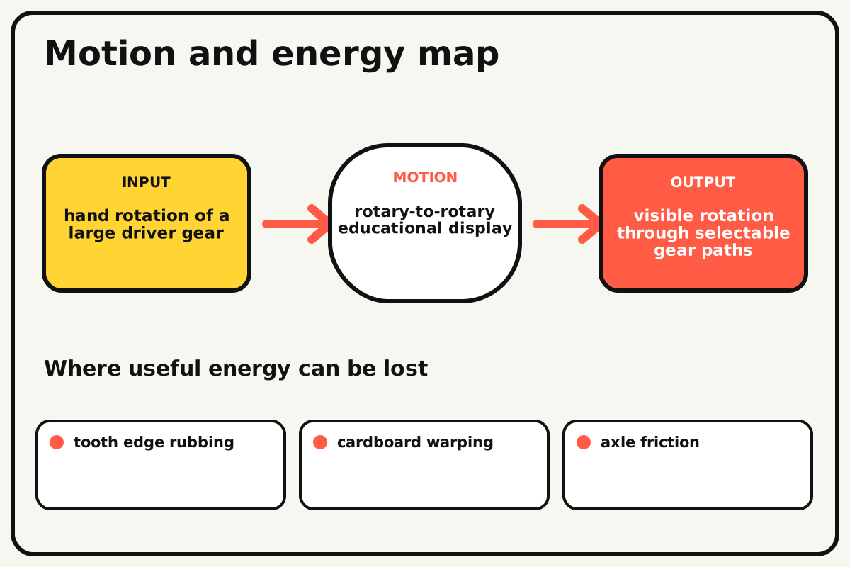
- Input
- hand rotation of a large driver gear
- Output
- visible rotation through selectable gear paths
- Motion
- rotary-to-rotary educational display
- Energy losses
- tooth edge rubbing, cardboard warping, axle friction, frame flex
Why this works
Consistent tooth pitch
Gears mesh only when tooth spacing along their pitch circles matches. Tooth count then sets pitch diameter and the speed ratio between gear pairs.
Look for: Mark one tooth on every gear and count contacts and rotations through each configured path.
Where the energy goes
Efficiency and losses
The ideal model leaves out tooth edge rubbing, cardboard warping, axle friction, frame flex. These effects turn some input energy into heat, sound, vibration, or unwanted motion, so measured performance will be lower than an ideal calculation.
Look for: Run the build slowly and locate the first place where tooth edge rubbing becomes visible or audible.
Math bite
Set center distance
Formula: center distance = (driver pitch diameter + driven pitch diameter) / 2
- Driver pitch diameter = 80 mm
- Driven pitch diameter = 160 mm
Substitute: distance = (80 + 160)/2 = 120 mm
Result: Axle centers should begin about 120 mm apart.
Final spacing needs a small running clearance.
Hand-cut tooth shape and cardboard thickness create error.
Make it behave
Test, troubleshoot, and tune
Controlled test
Start here: Turn each gear separately before completing a train.
Success looks like: All paths complete ten input turns without repeated binding and show expected direction.
Measure: Input-output turns, tight spots, and frame deflection.
Change: the axle center distance
Keep constant: gear pair, pitch, frame, speed, arrows, and turn count
- slightly loose
- calculated distance
- slightly tight
| Symptom | Likely cause | Confirm it | Fix |
|---|---|---|---|
| The mesh tightens once per turn | A gear is off-center or warped | Mark the tight angle | Recenter the hub and flatten the gear |
| Teeth skip everywhere | Center distance is wide or pitch differs | Compare tooth spacing with paper marks | Move axles closer or rebuild matching pitch |
| Compound gears rub | Stages share one plane or spacing is low | Turn the middle shaft alone | Add axial spacers and separate planes |
| The frame spreads | Bearing panels lack cross braces | Hold output lightly and observe centers | Add braces beside axles |
Choose your tradeoff
Cut tooth spacing consistently before refining tooth shape. Large cardboard gears need flat lamination and short axle spans; slight backlash is safer than a forced mesh.
Keep experimenting
Try another version
Two-gear board
Show one reduction and direction reversal.
Interchangeable slots
Build movable axle supports for fast ratio changes.
Efficiency display
Lift a tiny mass and compare ideal and measured work.
Build together
Classroom and access options
Classroom version
Teams can compare the axle center distance while keeping gear pair, pitch, frame, speed, arrows, and turn count. Assign builder, tester, recorder, and explainer roles; have each team predict the result before collecting three trials.
Access adaptations
- Pre-cut repeated pieces and mark fold lines with high-contrast ink.
- Use large tabs, binder clips, and tape for easier one-handed assembly.
- Use oversized high-contrast gears and tactile tooth markers at one reference tooth.
Reflect on the design
- How did the axle center distance change the measured result?
- Where did tooth edge rubbing affect the build most strongly?
- What evidence shows that consistent tooth pitch explains the motion?
- Which change would improve visible rotation through selectable gear paths without creating a new problem?
Glossary
- Consistent tooth pitch
- Gears mesh only when tooth spacing along their pitch circles matches.
- Input
- The action or energy supplied to a system; here it is hand rotation of a large driver gear.
- Output
- The useful response produced by a system; here it is visible rotation through selectable gear paths.
- Efficiency
- The fraction of input energy that becomes useful output instead of friction, sound, heat, or unwanted motion.
Build your dreams
One build can start the next.
Share what you learned, change one variable, and help another builder understand what worked.
Explore more guidesSources and build notes
An original BrickLabClips cardboard machine with dimensionally specified construction.
- Cardboard design verification: Dimensions, fold allowances, repeated-motion joints, and likely load paths received an editorial geometry review.
Written and edited by BrickLabClips. Published 2026-07-22; updated 2026-07-22.
Next builds
Related guides
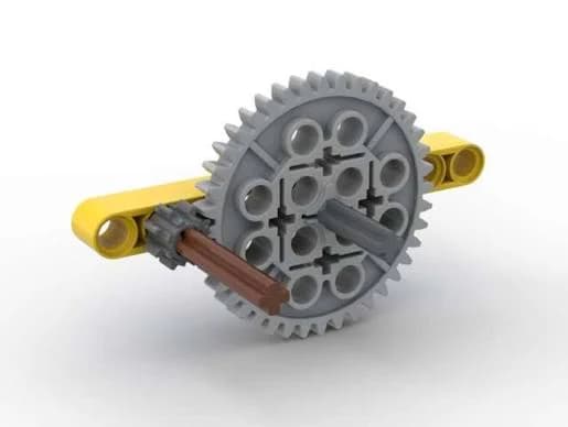
Gear Ratio Demonstrator
Turn one crank and compare how gear size changes output speed, direction, and turning force.
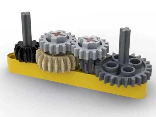
Compound Gear Train
Stack two gear reductions on a shared middle axle to create a large speed change in a compact frame.
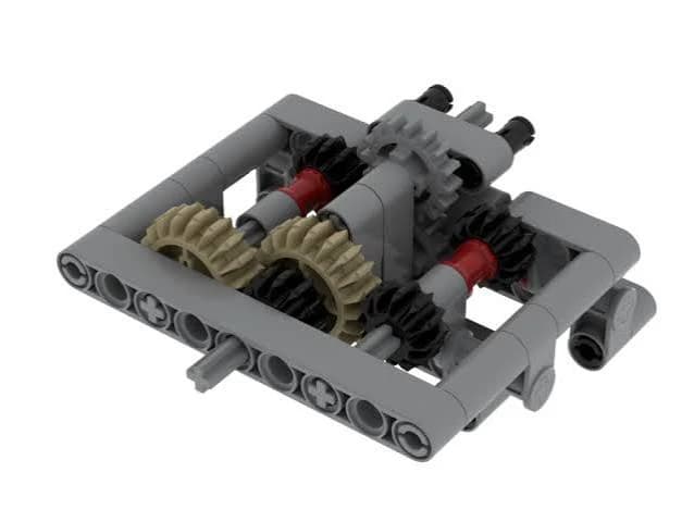
Idler Gear Direction Reverser
Add a middle idler gear to change output direction without changing the ideal speed ratio.