
- Difficulty
- Beginner
- Build time
- 45-60 min
- Estimated cost
- $0-$10
- Age range
- 10-16
- Workspace
- A clear desk or table
The finish line
What you will build
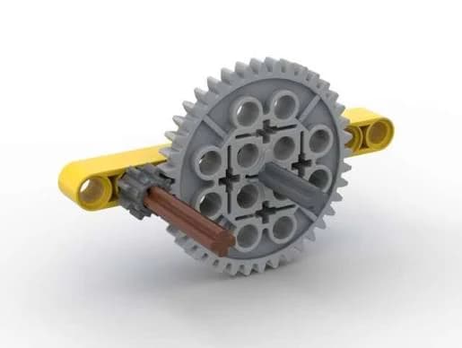
A successful demonstrator turns without gear skipping. With a 12-tooth driver and 36-tooth driven gear, the output completes about one turn for every three crank turns and rotates in the opposite direction.
Learning goals
- Identify the driver and driven gears in a simple train.
- Calculate an ideal gear ratio from tooth counts.
- Compare output speed and ideal torque after swapping the gears.
- Tune axle spacing to reduce friction without allowing teeth to skip.
Before you build
Materials, tools, and safety
Reuse-material cost: $0 with an existing parts bin. Supervision: Adult help recommended for builders under 10.
Tools
- Ruler
- Pencil
- Small piece of removable tape
Low-cost swaps
- Use any two meshing gears with clearly countable teeth and recalculate the ratio.
- Build a corrugated-cardboard frame with straw axle bearings when no brick-compatible frame pieces are available.
- Mark one tooth on each gear with removable tape instead of adding paper arrow flags.
Project-specific safety
- Keep hair, sleeves, and fingers clear of the meshing teeth while the crank is moving.
- Use only hand speed; spinning the gears with a motor can eject loose parts.
- Small gears and bushings are a choking hazard for young children.
Orient the build
Place the model so the crank is on your left. That is the input side. The axle on your right is the output side; the long beams are the front and back rails, and the tabletop is the bottom reference plane.
Build it
Step-by-step instructions
Step 1
Build a rigid base
Connect two long beams with at least three cross pieces so the frame cannot twist when held at one corner.
Leave an open strip through the middle so both gears remain visible during testing.
Builder checkpoint: Press gently on opposite corners. The frame should stay flat instead of rocking.
Step 2
Raise the input supports
Add matching upright supports near the left side of the base, one on the front rail and one directly behind it.
Choose holes at the same height so the input axle will cross the frame at a right angle.
Watch for: Offset supports make the axle diagonal, which adds friction before the gears even meet.
Step 3
Install the small driver
Slide the input axle through both supports and place the 12-tooth gear near the center of the frame.
Add one spacer on each side, leaving a paper-thin gap so the axle can rotate freely.
Builder checkpoint: The axle should coast briefly after a quick finger turn and should not slide sideways.
Step 4
Locate the output axle
Hold the 36-tooth gear against the driver and find the position where the teeth overlap to about half their depth.
Mark that output-axle location on both frame rails before adding supports.
Watch for: A tight mesh pinches the teeth; a loose mesh allows the gears to skip under load.
Step 5
Add the large driven gear
Build equal-height supports at the marked position and pass the second axle through them.
Secure the 36-tooth gear in line with the driver, then use spacers to limit side-to-side motion.
Builder checkpoint: Turn the small gear one full rotation. Every tooth should stay engaged without forcing the frame apart.
Step 6
Add the crank and flags
Attach the crank to the outer end of the input axle where your hand will not scrape the frame.
Tape one small arrow flag to each axle and point both arrows upward at the starting position.
Step 7
Run a slow mesh test
Turn the crank slowly through three complete rotations while watching the marked teeth.
Stop immediately if a gear lifts, binds, or pushes an axle support outward; correct alignment before continuing.
Watch for: Speed can hide a repeating tight spot. Diagnose at one slow turn every two seconds.
Step 8
Swap the ratio
Move the crank to the 36-tooth axle so the large gear becomes the driver and the small gear becomes the output.
Repeat the three-turn test and compare output rotations, turning effort, and noise.
Builder checkpoint: Both arrangements should rotate smoothly, with a clear change in speed and direction.
See the engineering
Why it works
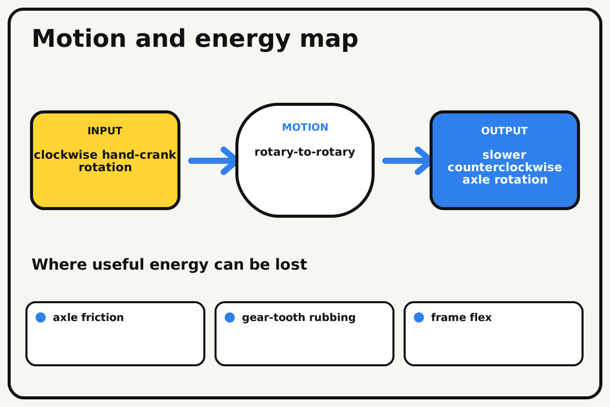
- Input
- clockwise hand-crank rotation
- Output
- slower counterclockwise axle rotation
- Motion
- rotary-to-rotary
- Energy losses
- axle friction, gear-tooth rubbing, frame flex, backlash
Why this works
Gear ratio
Meshing teeth move at the same contact speed. A gear with three times as many teeth must take three times as long to complete a turn, so speed decreases while ideal output torque increases.
Look for: Watch the arrow flags: three turns of the 12-tooth driver produce about one turn of the 36-tooth output.
Mechanical design note
Backlash and friction
Backlash is the small free movement between teeth when direction reverses. Some clearance prevents binding, but too much clearance makes motion imprecise and can let teeth skip.
Look for: Reverse the crank gently and notice the tiny delay before the output flag begins moving.
Math bite
Calculate the speed ratio
Formula: speed ratio = driven teeth / driver teeth
- Driven teeth = 36
- Driver teeth = 12
Substitute: speed ratio = 36 / 12 = 3
Result: The input turns three times for one ideal output turn.
At the same time, ideal output torque is about three times the input torque.
This ideal result ignores axle friction, tooth rubbing, backlash, and frame flex, so a real model delivers less than the ideal torque increase.
Make it behave
Test, troubleshoot, and tune
Controlled test
Start here: Turn the unloaded crank slowly for three input rotations.
Success looks like: The output makes about one rotation in the reduction setup, with no skipping or visible axle wobble.
Measure: Count input and output rotations and record the time for ten input turns.
Change: Driver and driven gear tooth counts
Keep constant: Keep the frame, axle spacing, crank speed, and paper flags unchanged.
- 12 driving 36 teeth
- 36 driving 12 teeth
- A same-size gear pair if available
| Symptom | Likely cause | Confirm it | Fix |
|---|---|---|---|
| The gears jam once per turn. | One gear or axle is bent or off-center. | Mark the tight point and rotate again to see whether it repeats at the same angle. | Reseat the gear, replace the bent axle, and square both supports. |
| Teeth skip under light finger resistance. | The axle spacing is too wide or the frame is flexing. | Watch whether the centers move apart when the output is held. | Move the supports one position closer or add a cross brace beside the gears. |
| The crank is hard to turn before the gears mesh. | Bushings are squeezing the frame or an axle is diagonal. | Remove the driven gear and test each axle separately. | Leave a thin side gap and align support holes at equal height. |
| The measured ratio is not exactly 3:1. | The flags were not reset or partial turns were counted. | Align both flags upward and repeat with twelve input turns. | Count full rotations from a shared start mark and average three trials. |
Choose your tradeoff
Tune one tradeoff at a time. Tighter spacing reduces backlash but raises friction; more bracing improves alignment but adds parts. Choose the loosest mesh that still holds under the load you plan to demonstrate.
Keep experimenting
Try another version
Same-size comparison
Mesh two equal gears and verify a 1:1 speed ratio with reversed direction.
Compound reduction
Add a second gear pair on a shared middle axle and predict the total ratio before testing.
Efficiency estimate
Lift a small known mass on the output axle and compare useful output work with input work over one cycle.
Build together
Classroom and access options
Classroom version
Give teams different gear pairs but the same frame footprint. Assign a builder, rotation counter, timer, and recorder. Teams predict the ratio, collect three trials, then arrange their models from fastest output to greatest ideal torque.
Access adaptations
- Use high-contrast arrow flags and tactile tape on the input axle.
- A partner can count rotations while the builder turns the larger crank.
- Replace the small crank with a wider handle for an easier grip.
Reflect on the design
- Why does the driven gear rotate in the opposite direction?
- What changed when the 36-tooth gear became the driver?
- Where did friction have the largest effect on your model?
- How would adding an idler gear change direction without changing the ideal ratio?
Glossary
- Driver gear
- The gear that receives the input motion.
- Driven gear
- The gear that receives motion from another gear.
- Torque
- A turning effect produced by force acting at a distance from an axis.
- Backlash
- Free movement between meshing teeth when rotation reverses.
Build your dreams
One build can start the next.
Share what you learned, change one variable, and help another builder understand what worked.
Explore more guidesSources and build notes
An original BrickLabClips interpretation of a standard spur-gear mechanism.
- Mechanical mechanism reference: Standard spur-gear kinematics; dimensions are specified and editorially reviewed.
- NASA STEM: Gears: Background reference for gear direction and ratios.
Written and edited by BrickLabClips. Published 2026-07-22; updated 2026-07-22.
Next builds
Related guides
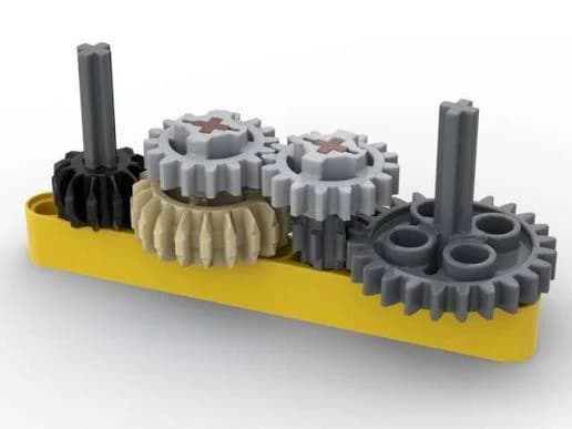
Compound Gear Train
Stack two gear reductions on a shared middle axle to create a large speed change in a compact frame.
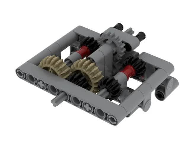
Idler Gear Direction Reverser
Add a middle idler gear to change output direction without changing the ideal speed ratio.
Classroom challengesGear Ratio Race
Configure equal vehicles for speed or pulling force, predict their ratios, and compare performance in two fair races.