
- Difficulty
- Intermediate
- Build time
- 60-90 min
- Estimated cost
- $0-$15
- Age range
- 11-17
- Workspace
- A clear table about 90 cm wide
The finish line
What you will build
The piston completes one full out-and-back stroke for every crank revolution and moves through its guide without binding across ten slow cycles.
Learning goals
- Identify how continuous rotation of a crank axle produces back-and-forth piston translation.
- Construct and explain a rotary-to-reciprocating linear system.
- Measure how the connecting-rod length changes performance.
- Diagnose losses caused by slider rubbing and pin friction.
Before you build
Materials, tools, and safety
Reuse-material cost: Usually under $5 with an existing kit. Supervision: Adult help recommended for sharp or heated tools.
Tools
- Ruler
- Removable tape for motion marks
Low-cost swaps
- Use equivalent brick-compatible parts from any kit.
- Use cardboard beams and straw bearings for a larger demonstration model.
- Make the slider from folded cardboard and use paper fasteners for the crank and rod pivots.
Project-specific safety
- Keep fingers, hair, and loose sleeves clear of moving parts.
- Turn the mechanism by hand; do not attach a high-speed motor.
- Turn slowly and keep fingers away from the crank pin and the piston end stops.
Orient the build
Place the build so continuous rotation of a crank axle is on your left and back-and-forth piston translation is on your right. Call the side facing you the front, the far side the back, the tabletop the bottom, and the opposite face the top.
Build it
Step-by-step instructions
Step 1
Build the crank frame
Brace two bearing walls around a low horizontal axle.
Leave open space on one side for the connecting rod.
Step 2
Assemble the linear guide
Create two parallel rails extending away from the crank center.
Check their spacing with the slider before fixing them.
Step 3
Make the slider
Build a compact block that travels between the rails with little side play.
Add a centered pivot hole facing the crank.
Builder checkpoint: After make the slider, the first subassembly should stay aligned when handled gently.
Step 4
Set the crank radius
Attach an offset pin to a wheel or short beam on the input axle.
Start with a radius near 3 modules.
Watch for: If this stage binds or drifts, inspect frame flex before adding more parts.
Step 5
Connect the rod
Join one rod end to the crank pin and the other to the slider pivot.
Use free pivots with collars that do not squeeze the rod.
Step 6
Check both dead centers
Rotate the crank until the rod and crank align at each stroke end.
Confirm the slider stops before hitting the guide ends.
Builder checkpoint: After check both dead centers, operate the build slowly and confirm that back-and-forth piston translation begins without binding.
Step 7
Brace against side load
Add top guides or cross braces where the slider tries to twist.
Retest one full turn after each brace.
Step 8
Run ten slow cycles
Mark the two extreme slider positions and rotate at a steady pace.
Listen for a repeating click or scrape at the same crank angle.
Builder checkpoint: At the final checkpoint, The piston completes one full out-and-back stroke for every crank revolution and moves through its guide without binding across ten slow cycles.
See the engineering
Why it works
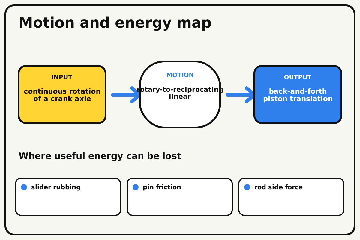
- Input
- continuous rotation of a crank axle
- Output
- back-and-forth piston translation
- Motion
- rotary-to-reciprocating linear
- Energy losses
- slider rubbing, pin friction, rod side force, frame flex
Why this works
Crank-slider kinematics
An offset crank pin follows a circle while the slider is constrained to a straight path. A connecting rod resolves the circular motion into changing linear position and side force.
Look for: Notice that piston speed falls to zero at each end of the stroke even though the crank keeps turning steadily.
Where the energy goes
Efficiency and losses
The ideal model leaves out slider rubbing, pin friction, rod side force, frame flex. These effects turn some input energy into heat, sound, vibration, or unwanted motion, so measured performance will be lower than an ideal calculation.
Look for: Run the build slowly and locate the first place where slider rubbing becomes visible or audible.
Math bite
Predict piston stroke
Formula: stroke = 2 × crank radius
- Crank radius = 30 mm
- Stroke is twice the radius
Substitute: stroke = 2 × 30 mm = 60 mm
Result: The piston should travel about 6 cm from one extreme to the other.
Changing rod length alters side force and timing shape but not the ideal two-radius stroke.
Clearance and joint flexibility can make the measured stroke slightly smaller.
Make it behave
Test, troubleshoot, and tune
Controlled test
Start here: Rotate the unloaded crank through one revolution over four seconds.
Success looks like: The slider reaches both marks once and completes an out-and-back cycle without contact at the ends.
Measure: Stroke distance and time for ten cycles.
Change: the connecting-rod length
Keep constant: crank radius, guide spacing, frame, and rotation rate
- short rod
- medium rod
- long rod
| Symptom | Likely cause | Confirm it | Fix |
|---|---|---|---|
| The mechanism locks near a stroke end | The rod is too short or the guide is offset | Turn to the lock point and inspect rod angle | Lengthen the rod or realign the guide centerline |
| The slider rocks in its guide | Side clearance is too large | Push the slider sideways while stopped | Add a second guide face with a small gap |
| Pins work loose | Collars are missing or side load is high | Watch the joint during one slow cycle | Add collars and increase rod length |
| Stroke is shorter than predicted | Crank radius was measured to an edge, not pin center | Measure axle center to pin center | Recalculate from the true pivot-center distance |
Choose your tradeoff
A longer connecting rod reduces slider side force but takes more space. A larger crank radius increases stroke while demanding longer guides and greater clearance at both dead centers.
Keep experimenting
Try another version
Position pointer
Replace the piston with a lightweight arrow on a rail.
Twin pistons
Add a second crank pin 180 degrees away to balance output motion.
Motion graph
Measure piston position every 30 degrees and plot a position-versus-angle curve.
Build together
Classroom and access options
Classroom version
Teams can compare the connecting-rod length while keeping crank radius, guide spacing, frame, and rotation rate. Assign builder, tester, recorder, and explainer roles; have each team predict the result before collecting three trials.
Access adaptations
- Use high-contrast tape to distinguish input and output parts.
- Replace a small crank with a wider handle for an easier grip.
- Use a large crank and colored end-position markers so the cycle can be followed visually or by touch while stopped.
Reflect on the design
- How did the connecting-rod length change the measured result?
- Where did slider rubbing affect the build most strongly?
- What evidence shows that crank-slider kinematics explains the motion?
- Which change would improve back-and-forth piston translation without creating a new problem?
Glossary
- Crank-slider kinematics
- An offset crank pin follows a circle while the slider is constrained to a straight path.
- Input
- The action or energy supplied to a system; here it is continuous rotation of a crank axle.
- Output
- The useful response produced by a system; here it is back-and-forth piston translation.
- Efficiency
- The fraction of input energy that becomes useful output instead of friction, sound, heat, or unwanted motion.
Build your dreams
One build can start the next.
Share what you learned, change one variable, and help another builder understand what worked.
Explore more guidesSources and build notes
An original BrickLabClips interpretation of a standard mechanical mechanism.
- Mechanism verification: Standard kinematics were checked for motion direction, constraint, clearance, and likely friction points.
Written and edited by BrickLabClips. Published 2026-07-22; updated 2026-07-22.