
- Difficulty
- Beginner
- Build time
- 35-55 min
- Estimated cost
- $0-$2
- Age range
- 10-16
- Workspace
- A clear table about 90 cm wide
The finish line
What you will build
The paper structure extends at least 40 cm beyond the desk and holds a 10-gram tip load for ten seconds without an extra floor support.
Learning goals
- Identify how downward load at the free tip produces bending resistance at the anchored end.
- Construct and explain a static load-to-controlled deflection system.
- Measure how cross-section shape changes performance.
- Diagnose losses caused by paper creasing and clamp slip.
Before you build
Materials, tools, and safety
Reuse-material cost: $0-$3 with reused materials. Supervision: Adult help recommended for sharp or heated tools.
Tools
- Ruler
- Pencil
- Scissors
- Timer or phone stopwatch
Low-cost swaps
- Use reclaimed paper and packaging while keeping material limits equal for every team.
- Replace metal test weights with labeled bags of coins or washers.
- Use identical newspaper rectangles and clothespins while keeping limits equal for all teams.
Project-specific safety
- Keep load and drop tests below shoulder height and away from faces.
- Clear the test zone before releasing moving objects or suspended loads.
- Use a light bagged load, keep feet away from the drop zone, and protect the desk edge from clamps.
Orient the build
Place the build so downward load at the free tip is on your left and bending resistance at the anchored end is on your right. Call the side facing you the front, the far side the back, the tabletop the bottom, and the opposite face the top.
Build it
Step-by-step instructions
Step 1
Set the rules
Limit each team to three sheets, 50 cm tape, and two clips.
Define overhang from desk edge to load point.
Step 2
Test a flat control
Clamp one flat sheet with 20 cm overhang and add the load.
Record deflection after ten seconds.
Step 3
Choose a section
Fold paper into a tube, channel, or triangular beam.
Keep the cross-section consistent.
Builder checkpoint: After choose a section, the first subassembly should stay aligned when handled gently.
Step 4
Join the length
Overlap sheets by 4 cm and tape along both faces.
Avoid a hinge-like single tape line.
Watch for: If this stage binds or drifts, inspect local buckling before adding more parts.
Step 5
Reinforce the root
Add a sleeve or deeper section near the desk edge.
Leave the distant tip light.
Step 6
Attach the load point
Tape a small loop at the center of the free end.
Prevent the load from pulling sideways.
Builder checkpoint: After attach the load point, operate the build slowly and confirm that bending resistance at the anchored end begins without binding.
Step 7
Increase overhang
Move outward in 5 cm increments and hold ten seconds each.
Stop at visible permanent damage.
Step 8
Measure and explain
Record maximum passing length, root deflection, and failure mode.
Sketch the final cross-section.
Builder checkpoint: At the final checkpoint, The paper structure extends at least 40 cm beyond the desk and holds a 10-gram tip load for ten seconds without an extra floor support.
See the engineering
Why it works
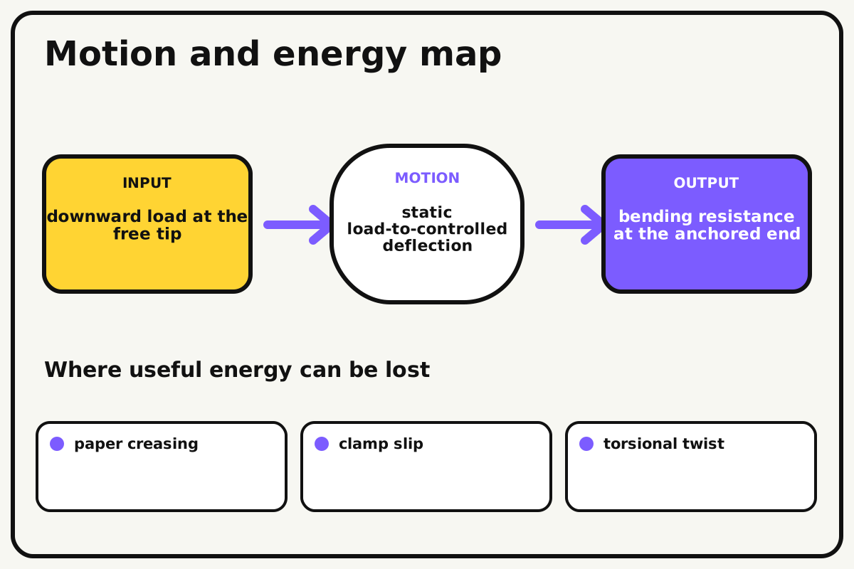
- Input
- downward load at the free tip
- Output
- bending resistance at the anchored end
- Motion
- static load-to-controlled deflection
- Energy losses
- paper creasing, clamp slip, torsional twist, local buckling
Why this works
Cantilever bending moment
The turning effect at the support equals load force times distance. Moving the same load farther from the desk increases the demand on the paper and clamp.
Look for: Sight along the structure and find whether failure begins as vertical sag, sideways twist, or clamp slip.
Where the energy goes
Efficiency and losses
The ideal model leaves out paper creasing, clamp slip, torsional twist, local buckling. These effects turn some input energy into heat, sound, vibration, or unwanted motion, so measured performance will be lower than an ideal calculation.
Look for: Run the build slowly and locate the first place where paper creasing becomes visible or audible.
Math bite
Compare bending moment
Formula: moment = force × distance
- Load force = 0.10 N
- Distance = 0.40 m
Substitute: moment = 0.10 × 0.40 = 0.040 N·m
Result: The support resists about 0.040 newton-metres ideally.
Doubling distance doubles the moment from the same load.
Paper weight and dynamic loading add extra demand.
Make it behave
Test, troubleshoot, and tune
Controlled test
Start here: Test a flat 20 cm overhang as a control.
Success looks like: The final structure holds 10 grams at 40 cm for ten seconds.
Measure: Maximum overhang, tip deflection, failure mode, and material use.
Change: cross-section shape
Keep constant: paper count, tape length, clamps, load, hold time, and desk
- flat
- channel
- tube or triangle
| Symptom | Likely cause | Confirm it | Fix |
|---|---|---|---|
| The root creases | Section is shallow near the clamp | Inspect the first permanent fold | Deepen or sleeve the root |
| The beam twists | Cross-section is open or load off-center | View from the end | Close the section and center the load |
| It slides from the desk | Clamp contact is small | Mark the paper at the edge | Increase anchored length without adding clips |
| A joint folds | Overlap is short or tape acts as a hinge | Bend gently at each joint | Increase overlap and tape opposite faces |
Choose your tradeoff
Put depth and reinforcement near the support where moment is greatest, while keeping the distant end light. More anchored paper improves grip but reduces available overhang.
Keep experimenting
Try another version
Thirty-centimetre target
Use the same load with no joints.
Efficiency score
Divide passing overhang by paper mass.
Deflection graph
Plot tip sag against distance in 5 cm steps.
Build together
Classroom and access options
Classroom version
Teams can compare cross-section shape while keeping paper count, tape length, clamps, load, hold time, and desk. Assign builder, tester, recorder, and explainer roles; have each team predict the result before collecting three trials.
Access adaptations
- Assign varied roles such as designer, builder, tester, recorder, and presenter.
- Provide pre-measured materials and a visual checklist when helpful.
- Pre-mark fold lines and offer measuring, folding, loading, and documenting roles.
Reflect on the design
- How did cross-section shape change the measured result?
- Where did paper creasing affect the build most strongly?
- What evidence shows that cantilever bending moment explains the motion?
- Which change would improve bending resistance at the anchored end without creating a new problem?
Glossary
- Cantilever bending moment
- The turning effect at the support equals load force times distance.
- Input
- The action or energy supplied to a system; here it is downward load at the free tip.
- Output
- The useful response produced by a system; here it is bending resistance at the anchored end.
- Efficiency
- The fraction of input energy that becomes useful output instead of friction, sound, heat, or unwanted motion.
Build your dreams
One build can start the next.
Share what you learned, change one variable, and help another builder understand what worked.
Explore more guidesSources and build notes
A common classroom engineering challenge implemented with original constraints, diagrams, and measurement guidance.
- Classroom challenge basis: A controlled-variable engineering activity with original constraints, scoring ideas, and measurement guidance.
Written and edited by BrickLabClips. Published 2026-07-22; updated 2026-07-22.