
- Difficulty
- Beginner
- Build time
- 35-60 min
- Estimated cost
- $0-$3
- Age range
- 10-16
- Workspace
- A clear table about 90 cm wide
The finish line
What you will build
One beam spans 20 cm and supports at least 500 grams at midspan for ten seconds with a documented failure mode.
Learning goals
- Identify how downward midspan test load produces structural resistance across two supports.
- Construct and explain a static load-to-beam deflection system.
- Measure how cross-section shape changes performance.
- Diagnose losses caused by local buckling and crease damage.
Before you build
Materials, tools, and safety
Reuse-material cost: $0-$3 with reused materials. Supervision: Adult help recommended for sharp or heated tools.
Tools
- Ruler
- Pencil
- Scissors
- Timer or phone stopwatch
Low-cost swaps
- Use reclaimed paper and packaging while keeping material limits equal for every team.
- Replace metal test weights with labeled bags of coins or washers.
- Cut identical rectangles from cereal boxes when index cards are unavailable.
Project-specific safety
- Keep load and drop tests below shoulder height and away from faces.
- Clear the test zone before releasing moving objects or suspended loads.
- Keep test supports low, add mass gradually, and use a tray to catch falling bagged weights.
Orient the build
Place the build so downward midspan test load is on your left and structural resistance across two supports is on your right. Call the side facing you the front, the far side the back, the tabletop the bottom, and the opposite face the top.
Build it
Step-by-step instructions
Step 1
Define four designs
Choose flat stack, channel, closed tube, and accordion.
Sketch the end view of each.
Step 2
Build the flat control
Stack three cards and use equal tape at each end.
Do not pre-crease the span.
Step 3
Build the channel
Fold 2 cm walls along two long edges of three joined cards.
Keep wall heights equal.
Builder checkpoint: After build the channel, the first subassembly should stay aligned when handled gently.
Step 4
Build the tube
Fold and tape a rectangular closed section using the same card count.
Align the seam along one side.
Watch for: If this stage binds or drifts, inspect off-center loading before adding more parts.
Step 5
Build the accordion
Make equal alternating folds across three connected cards.
Keep the top surface level enough for the cup.
Step 6
Set the test rig
Space books exactly 20 cm and mark midspan.
Place a catch tray beneath.
Builder checkpoint: After set the test rig, operate the build slowly and confirm that structural resistance across two supports begins without binding.
Step 7
Load each beam
Add 100-gram bags every five seconds until failure or 1 kg.
Record deflection at 500 grams.
Step 8
Compare failures
Photograph or sketch the first damaged location.
Rank strength and mass efficiency.
Builder checkpoint: At the final checkpoint, One beam spans 20 cm and supports at least 500 grams at midspan for ten seconds with a documented failure mode.
See the engineering
Why it works
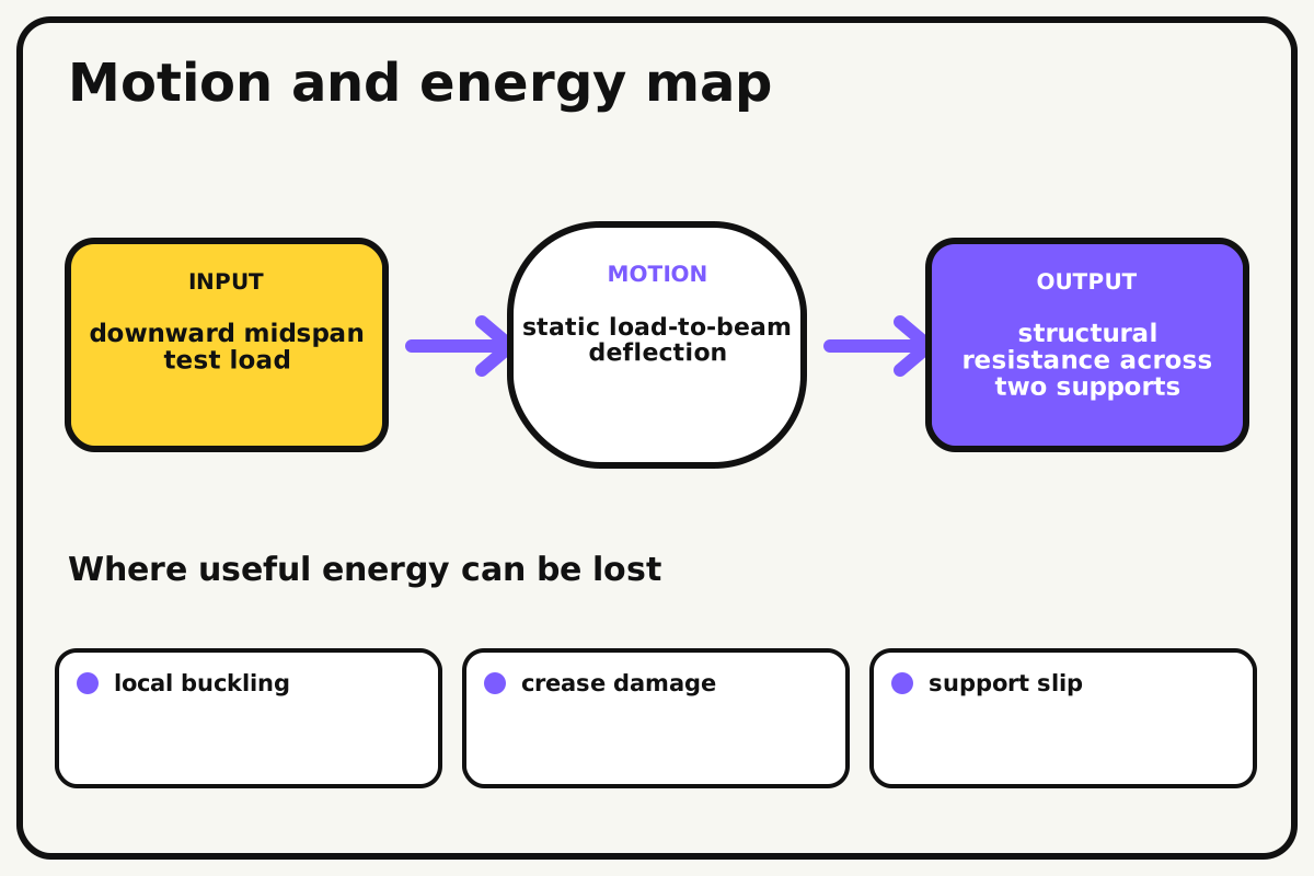
- Input
- downward midspan test load
- Output
- structural resistance across two supports
- Motion
- static load-to-beam deflection
- Energy losses
- local buckling, crease damage, support slip, off-center loading
Why this works
Cross-section stiffness
A deeper beam places more material farther from the neutral axis, increasing bending stiffness. Thin walls can still buckle before the material reaches its full strength.
Look for: Mark the top and bottom surfaces and note whether failure starts in top compression, bottom tension, or a side-wall buckle.
Where the energy goes
Efficiency and losses
The ideal model leaves out local buckling, crease damage, support slip, off-center loading. These effects turn some input energy into heat, sound, vibration, or unwanted motion, so measured performance will be lower than an ideal calculation.
Look for: Run the build slowly and locate the first place where local buckling becomes visible or audible.
Math bite
Compare load-to-mass efficiency
Formula: efficiency = supported mass / beam mass
- Supported mass = 800 g
- Beam mass = 15 g
Substitute: efficiency = 800 / 15 = 53.3
Result: The beam supports about 53 times its own mass.
This compares designs that use different tape amounts.
Scale readings and failure thresholds are approximate.
Make it behave
Test, troubleshoot, and tune
Controlled test
Start here: Load the flat control first in 100-gram steps.
Success looks like: At least one shaped beam supports 500 grams for ten seconds.
Measure: Failure load, deflection at 500 grams, beam mass, and failure location.
Change: cross-section shape
Keep constant: card count, span, tape allowance, loading cup, rate, and weights
- flat
- channel
- closed tube
- accordion
| Symptom | Likely cause | Confirm it | Fix |
|---|---|---|---|
| The load cup punches through | Contact area is too small | Inspect a local top dent | Use one identical load-spreader card |
| One wall buckles early | Fold heights or loading are uneven | View the end section | Refold symmetrically and center load |
| The beam slides | Support friction is inconsistent | Mark end positions | Add equal nonslip pads |
| Tape fails before paper | Seams carry peel load | Watch the seam edge | Place the seam on a side and increase overlap |
Choose your tradeoff
Increase section depth without creating unsupported walls. Closed sections resist twisting well, but a poorly placed seam can become the first failure.
Keep experimenting
Try another version
Two-shape comparison
Test flat and channel only.
One-kilogram target
Redesign the strongest section without more cards.
Deflection stiffness
Calculate load divided by measured deflection before failure.
Build together
Classroom and access options
Classroom version
Teams can compare cross-section shape while keeping card count, span, tape allowance, loading cup, rate, and weights. Assign builder, tester, recorder, and explainer roles; have each team predict the result before collecting three trials.
Access adaptations
- Assign varied roles such as designer, builder, tester, recorder, and presenter.
- Provide pre-measured materials and a visual checklist when helpful.
- Provide folding jigs, bold cross-section diagrams, and team roles for loading, counting, and observing.
Reflect on the design
- How did cross-section shape change the measured result?
- Where did local buckling affect the build most strongly?
- What evidence shows that cross-section stiffness explains the motion?
- Which change would improve structural resistance across two supports without creating a new problem?
Glossary
- Cross-section stiffness
- A deeper beam places more material farther from the neutral axis, increasing bending stiffness.
- Input
- The action or energy supplied to a system; here it is downward midspan test load.
- Output
- The useful response produced by a system; here it is structural resistance across two supports.
- Efficiency
- The fraction of input energy that becomes useful output instead of friction, sound, heat, or unwanted motion.
Build your dreams
One build can start the next.
Share what you learned, change one variable, and help another builder understand what worked.
Explore more guidesSources and build notes
A common classroom engineering challenge implemented with original constraints, diagrams, and measurement guidance.
- Classroom challenge basis: A controlled-variable engineering activity with original constraints, scoring ideas, and measurement guidance.
Written and edited by BrickLabClips. Published 2026-07-22; updated 2026-07-22.