
- Difficulty
- Advanced
- Build time
- 120-180 min
- Estimated cost
- $0-$25
- Age range
- 13-18
- Workspace
- A clear table about 90 cm wide
The finish line
What you will build
At controlled hand speeds, both masses rise symmetrically, the pointer increases with speed, and all parts return after the crank stops.
Learning goals
- Identify how low-speed rotation of a vertical spindle produces radial mass motion and vertical pointer rise.
- Construct and explain a rotary speed-to-radial and linear displacement system.
- Measure how the rotational speed changes performance.
- Diagnose losses caused by hinge friction and air drag.
Before you build
Materials, tools, and safety
Reuse-material cost: Usually under $5 with an existing kit. Supervision: Adult help recommended for sharp or heated tools.
Tools
- Ruler
- Removable tape for motion marks
Low-cost swaps
- Use equivalent brick-compatible parts from any kit.
- Use cardboard beams and straw bearings for a larger demonstration model.
- Use a large cardboard spindle with soft clay masses and string links inside a clear tall box.
Project-specific safety
- Keep fingers, hair, and loose sleeves clear of moving parts.
- Turn the mechanism by hand; do not attach a high-speed motor.
- Use soft masses under 10 grams, a complete guard ring, and hand speed only; never attach a motor.
Orient the build
Place the build so low-speed rotation of a vertical spindle is on your left and radial mass motion and vertical pointer rise is on your right. Call the side facing you the front, the far side the back, the tabletop the bottom, and the opposite face the top.
Build it
Step-by-step instructions
Step 1
Build the guarded tower
Support a vertical spindle in top and bottom bearings inside a wide guard ring.
Brace the tower against wobble.
Step 2
Make matched upper arms
Build two equal hinged links opposite each other on the spindle hub.
Overlay them before installing.
Step 3
Attach equal soft masses
Secure one mass at each arm end with redundant connections.
Check balance while stopped.
Builder checkpoint: After attach equal soft masses, the first subassembly should stay aligned when handled gently.
Step 4
Add lower links
Connect each arm to opposite sides of a loose vertical sleeve.
Keep both link lengths equal.
Watch for: If this stage binds or drifts, inspect sleeve rubbing before adding more parts.
Step 5
Install the pointer
Attach a light indicator to the sleeve beside a height scale.
Ensure the sleeve slides without rotating into the arms.
Step 6
Check full clearance
Move masses outward by hand and rotate one cycle.
Confirm links and sleeve clear the guard.
Builder checkpoint: After check full clearance, operate the build slowly and confirm that radial mass motion and vertical pointer rise begins without binding.
Step 7
Run low-speed trials
Turn at about one revolution per second for ten seconds.
Wait for steady pointer height before recording.
Step 8
Increase gradually
Repeat at two and three turns per second only if balanced and secure.
Stop at the first severe vibration.
Builder checkpoint: At the final checkpoint, At controlled hand speeds, both masses rise symmetrically, the pointer increases with speed, and all parts return after the crank stops.
See the engineering
Why it works
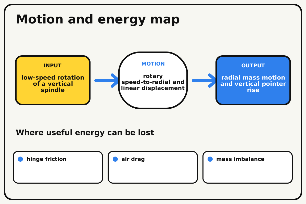
- Input
- low-speed rotation of a vertical spindle
- Output
- radial mass motion and vertical pointer rise
- Motion
- rotary speed-to-radial and linear displacement
- Energy losses
- hinge friction, air drag, mass imbalance, sleeve rubbing
Why this works
Speed-dependent radial force
Rotating masses require inward centripetal force. As speed rises, link tension increases and the masses move outward until gravity and linkage geometry balance the required force.
Look for: Count crank turns over ten seconds and compare that speed with pointer height after motion settles.
Where the energy goes
Efficiency and losses
The ideal model leaves out hinge friction, air drag, mass imbalance, sleeve rubbing. These effects turn some input energy into heat, sound, vibration, or unwanted motion, so measured performance will be lower than an ideal calculation.
Look for: Run the build slowly and locate the first place where hinge friction becomes visible or audible.
Math bite
Compare centripetal force
Formula: F = m × r × ω²
- Mass m = 0.008 kg
- Radius r = 0.06 m
- Angular speed ω = 6 rad/s
Substitute: F = 0.008 × 0.06 × 6² = 0.0173 N
Result: Each mass needs about 0.017 newtons inward at this speed.
Doubling speed would quadruple ideal required force.
Link angles, gravity, drag, and hand-speed variation affect height.
Make it behave
Test, troubleshoot, and tune
Controlled test
Start here: Rotate at about one turn per second for ten seconds behind the guard.
Success looks like: Both masses rise to similar heights without severe vibration and return after stopping.
Measure: Crank turns in ten seconds and steady pointer height.
Change: the rotational speed
Keep constant: masses, radius, arms, guard, spindle, and trial duration
- about 1 turn/s
- about 2 turns/s
- about 3 turns/s if stable
| Symptom | Likely cause | Confirm it | Fix |
|---|---|---|---|
| The tower shakes strongly | Masses, links, or pivot friction are unequal | Compare opposite assemblies while stopped | Match masses and lengths before retesting |
| The pointer does not rise | Sleeve binds or lower links are disconnected | Lift sleeve by hand with spindle stopped | Align the guide and free pivots |
| One mass stays low | Its hinge is tight | Move each arm separately | Add running clearance and equal spacers |
| The sleeve stays high after stopping | Friction exceeds return force | Disconnect links and slide manually | Reduce guide rubbing and mass preload |
Choose your tradeoff
Balance before speed. Equal masses and pivots create a readable signal; more speed increases force rapidly, so use longer observation at modest hand rates rather than chasing height.
Keep experimenting
Try another version
Two-arm spinner
Observe radial motion without a sleeve.
Calibrated scale
Mark pointer height at three measured speeds.
Feedback linkage
Let the sleeve move a paper throttle indicator and discuss closed-loop control.
Build together
Classroom and access options
Classroom version
Teams can compare the rotational speed while keeping masses, radius, arms, guard, spindle, and trial duration. Assign builder, tester, recorder, and explainer roles; have each team predict the result before collecting three trials.
Access adaptations
- Use high-contrast tape to distinguish input and output parts.
- Replace a small crank with a wider handle for an easier grip.
- Add an audible paper pointer that taps labeled low, medium, and high cards.
Reflect on the design
- How did the rotational speed change the measured result?
- Where did hinge friction affect the build most strongly?
- What evidence shows that speed-dependent radial force explains the motion?
- Which change would improve radial mass motion and vertical pointer rise without creating a new problem?
Glossary
- Speed-dependent radial force
- Rotating masses require inward centripetal force.
- Input
- The action or energy supplied to a system; here it is low-speed rotation of a vertical spindle.
- Output
- The useful response produced by a system; here it is radial mass motion and vertical pointer rise.
- Efficiency
- The fraction of input energy that becomes useful output instead of friction, sound, heat, or unwanted motion.
Build your dreams
One build can start the next.
Share what you learned, change one variable, and help another builder understand what worked.
Explore more guidesSources and build notes
An original BrickLabClips interpretation of a standard mechanical mechanism.
- Mechanism verification: Standard kinematics were checked for motion direction, constraint, clearance, and likely friction points.
Written and edited by BrickLabClips. Published 2026-07-22; updated 2026-07-22.