
- Difficulty
- Intermediate
- Build time
- 75-110 min
- Estimated cost
- $0-$8
- Age range
- 11-17
- Workspace
- A clear table about 90 cm wide
The finish line
What you will build
The bridge spans 40 cm, supports at least 500 grams for ten seconds, and shows a documented tension or compression failure mode.
Learning goals
- Identify how downward midspan test load produces axial forces carried to two supports.
- Construct and explain a static loading with structural deflection system.
- Measure how the side-truss diagonal pattern changes performance.
- Diagnose losses caused by joint slip and straw buckling.
Before you build
Materials, tools, and safety
Reuse-material cost: $0-$3 with reused materials. Supervision: Adult help recommended for sharp or heated tools.
Tools
- Ruler
- Pencil
- Scissors
- Masking tape
Low-cost swaps
- Use clean recycled packaging whenever it has similar stiffness.
- Substitute paper clips, binder clips, or twist ties for specialty fasteners.
- Roll paper tubes of equal length when plastic straws are unavailable.
Project-specific safety
- Wear eye protection when stretched elastic, magnets, or spinning parts are present.
- Test at floor or tabletop height and keep the path clear of people.
- Keep the bridge low over a tray, add masses gradually, and keep feet and hands away from falling loads.
Orient the build
Place the build so downward midspan test load is on your left and axial forces carried to two supports is on your right. Call the side facing you the front, the far side the back, the tabletop the bottom, and the opposite face the top.
Build it
Step-by-step instructions
Step 1
Draw a full-size side layout
Mark a 40 cm span, 10 cm height, and equal triangular panels.
Use the drawing for both trusses.
Step 2
Cut matched members
Trim straws to fit between joint centers and group equal lengths.
Avoid crushing the ends.
Step 3
Build the first truss
Tape members directly over the layout with compact joints.
Keep top and bottom chords straight.
Builder checkpoint: After build the first truss, the first subassembly should stay aligned when handled gently.
Step 4
Duplicate the second truss
Build a mirror copy over the same guide.
Overlay finished sides to compare geometry.
Watch for: If this stage binds or drifts, inspect asymmetric load before adding more parts.
Step 5
Connect the deck
Stand trusses parallel and tape the deck between their lower chords.
Keep spacing constant along the span.
Step 6
Add cross bracing
Join top chords with X or diagonal braces in at least three locations.
Check the bridge resists twisting.
Builder checkpoint: After add cross bracing, operate the build slowly and confirm that axial forces carried to two supports begins without binding.
Step 7
Run a preload test
Center an empty cup, then add 100 grams.
Measure midspan deflection and inspect joints.
Step 8
Load to target
Add 100-gram steps up to 500 grams or first failure.
Stop after ten seconds at each level and record the first deformation.
Builder checkpoint: At the final checkpoint, The bridge spans 40 cm, supports at least 500 grams for ten seconds, and shows a documented tension or compression failure mode.
See the engineering
Why it works
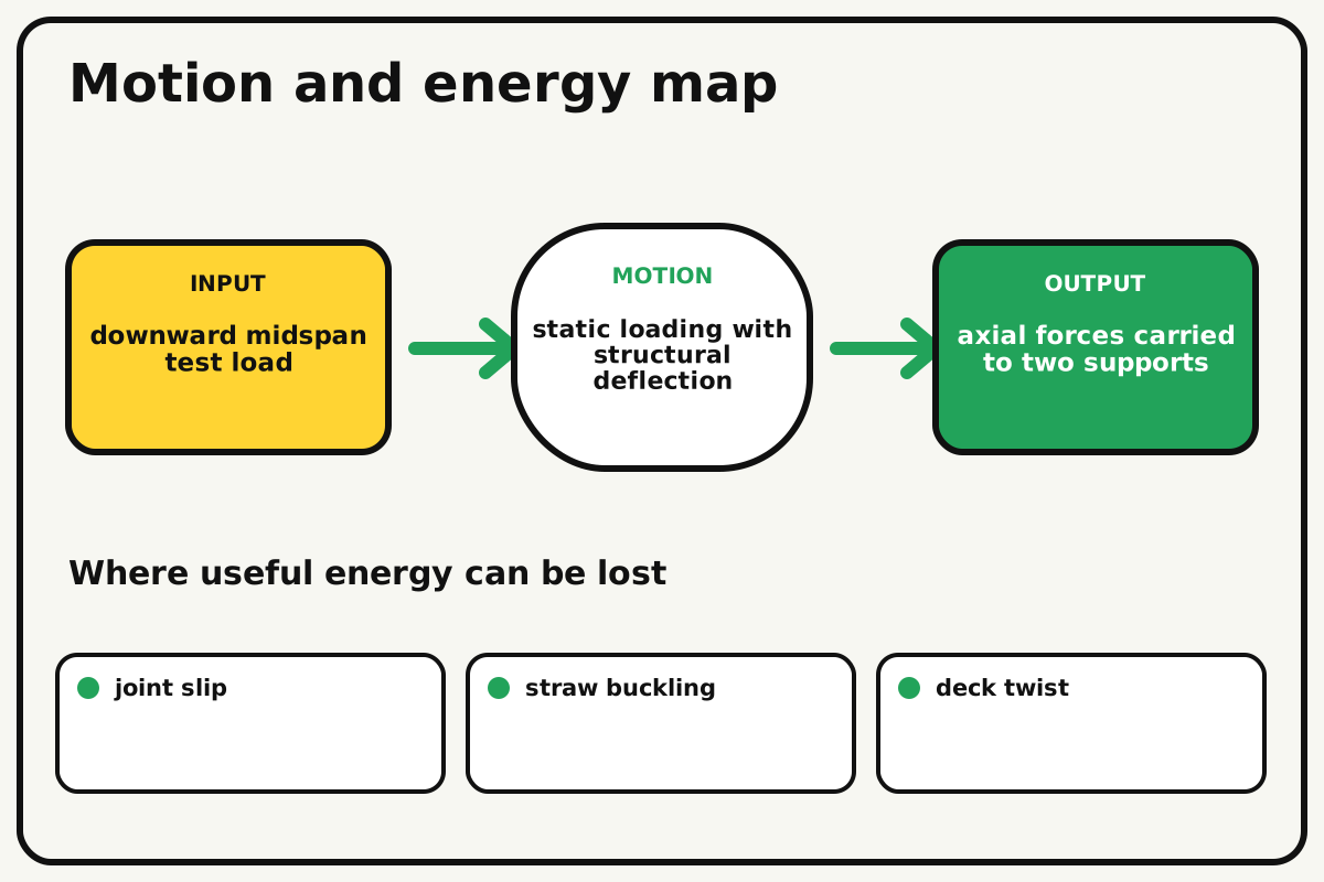
- Input
- downward midspan test load
- Output
- axial forces carried to two supports
- Motion
- static loading with structural deflection
- Energy losses
- joint slip, straw buckling, deck twist, asymmetric load
Why this works
Triangulated load paths
Ideal pin-jointed trusses carry loads mainly as tension or compression along members. Triangles preserve shape, while slender compression straws need bracing against buckling.
Look for: Mark likely compression members and watch which one bows before the bridge loses capacity.
Where the energy goes
Efficiency and losses
The ideal model leaves out joint slip, straw buckling, deck twist, asymmetric load. These effects turn some input energy into heat, sound, vibration, or unwanted motion, so measured performance will be lower than an ideal calculation.
Look for: Run the build slowly and locate the first place where joint slip becomes visible or audible.
Math bite
Find load per support
Formula: support reaction = centered load / 2
- Total centered load = 500 g
- Two symmetric supports
Substitute: reaction = 500/2 = 250 g equivalent at each support
Result: Each support carries about half the centered load.
Internal member forces can be much larger than this simple reaction.
The relation assumes symmetric geometry and centered loading.
Make it behave
Test, troubleshoot, and tune
Controlled test
Start here: Place an empty loading cup at exact midspan before adding masses.
Success looks like: The bridge spans 40 cm and supports 500 grams for ten seconds.
Measure: Maximum load, midspan deflection, and first failure location.
Change: the side-truss diagonal pattern
Keep constant: span, straw count, tape, deck, support, and loading rate
- vertical panels
- alternating diagonals
- X-braced panels
| Symptom | Likely cause | Confirm it | Fix |
|---|---|---|---|
| The top chord bows | Compression length is too long | Watch the top edge during loading | Add panel-point bracing |
| One truss carries more | Deck or load is off-center | Measure cup distance to both sides | Recenter and stiffen cross connections |
| Joints peel | Tape area or wrap direction is weak | Inspect the first opening joint | Use compact wraps around both members |
| The bridge twists | Cross bracing is missing | Push one top chord sideways when unloaded | Add top and end bracing |
Choose your tradeoff
Shorten unbraced compression lengths and keep joints centered on the member axes. Extra tape adds joint strength and dead weight, so use compact wraps rather than large flat patches.
Keep experimenting
Try another version
Twenty-centimetre truss
Build one short truss and test by hand.
Strength-to-mass
Divide supported mass by bridge mass.
Moving load
Roll a fixed mass across and map deflection.
Build together
Classroom and access options
Classroom version
Teams can compare the side-truss diagonal pattern while keeping span, straw count, tape, deck, support, and loading rate. Assign builder, tester, recorder, and explainer roles; have each team predict the result before collecting three trials.
Access adaptations
- Offer pre-cut parts and tactile or high-contrast measurement marks.
- Split roles so one builder can hold, another assemble, and another measure.
- Use a full-size truss layout and color-code tension and compression predictions.
Reflect on the design
- How did the side-truss diagonal pattern change the measured result?
- Where did joint slip affect the build most strongly?
- What evidence shows that triangulated load paths explains the motion?
- Which change would improve axial forces carried to two supports without creating a new problem?
Glossary
- Triangulated load paths
- Ideal pin-jointed trusses carry loads mainly as tension or compression along members.
- Input
- The action or energy supplied to a system; here it is downward midspan test load.
- Output
- The useful response produced by a system; here it is axial forces carried to two supports.
- Efficiency
- The fraction of input energy that becomes useful output instead of friction, sound, heat, or unwanted motion.
Build your dreams
One build can start the next.
Share what you learned, change one variable, and help another builder understand what worked.
Explore more guidesSources and build notes
A familiar household engineering activity implemented with original instructions and controlled tests.
- Classroom engineering basis: A common educational challenge implemented with original dimensions, tests, diagrams, and instructions.
Written and edited by BrickLabClips. Published 2026-07-22; updated 2026-07-22.